background image

101-A00    page 2/12 

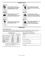
SAFETY DATA 


Failure to disconnect and lockout 
electrical power or engine drive before 
attempting maintenance can cause 
severe personal injury or death 


Failure to disconnect and lockout 
electrical power before attempting 
maintenance can cause shock, burns or 
death 


Hazardous 

machinery can 

cause serious 

personal injury. 


Hazardous voltage. 

Can shock, burn or 

cause death. 


If pumping hazardous or toxic fluids, 
system must be flushed and 
decontaminated, inside and out, prior to 
performing service or maintenance 


Disconnecting fluid or pressure 
containment components during pump 
operation can cause serious personal 
injury, death or major property damage 


Hazardous or toxic 

fluids can cause 

serious injury. 


Hazardous pressure 

can cause serious 

personal injury or 

property damage


Operation without guards in place can 
cause serious personal injury, major 
property damage, or death. 


Failure to relieve system pressure prior 
to performing pump service or 
maintenance can cause serious 
personal injury or property damage. 


Do not operate 

without guard in 

place 


Hazardous pressure 

can cause serious 

personal injury or 

property damage


PUMP DATA 


PUMP IDENTIFICATION 

A pump Identification tag, containing the pump serial number, I.D. number, and model designation, is attached to each pump.  It is 
recommended that the data from this tag be recorded and filed for future reference. If replacement parts are needed, or if 
information pertaining to the pump is required, this data must be furnished to a Blackmer representative. 


TECHNICAL DATA 


XF1, XB1 

XF1P, XB1P 

Maximum Pump Speed 

1,750 RPM 

1,750 RPM 

Maximum Temperature 

240°F 

(115°C) 

240°F 

(115°C) 

Maximum Viscosity 

100 SSU 

(20 cP) 

100 SSU 

(20 cP) 

Maximum Differential 
Pressure 

125 psi 

(8.6 Bar) 

125 psi 

(8.6 Bar) 

Maximum Working 
Pressure 

350 psi 

(24.1 Bar) 

350 psi 

(24.1 Bar) 


Technical Data is for standard materials of 
construction.  Consult Blackmer Material Specs for 
optional materials of construction. 

 
cP (centipoise) = centistokes at fluid specific gravity of 1.0 

INITIAL START UP INFORMATION 

Model No.: ____________________________________ 

Serial No.:  ____________________________________ 

ID No.:  _______________________________________ 

Date of Installation: _____________________________ 

Pressure Gauge Reading: 
________________________ 

Vacuum Gauge Reading: ________________________ 

Flow Rate: ____________________________________ 


Summary of Contents for XB1A

Page 1: ...a SAFETY ALERT SYMBOL When you see this symbol on the product or in the manual look for one of the following signal words and be alert to the potential for personal injury death or major property dam...

Page 2: ...ressure can cause serious personal injury or property damage PUMP DATA PUMP IDENTIFICATION A pump Identification tag containing the pump serial number I D number and model designation is attached to e...

Page 3: ...6m from the pump and have a net open area of at least four times the area of the intake piping Strainers must be cleaned regularly to avoid pump starvation 4 The intake and discharge piping system mus...

Page 4: ...or rebuilt pumps Both angular and parallel coupling alignment MUST be maintained between the pump gear motor etc in accordance with manufacturer s instructions See Figure 5 1 Parallel alignment The u...

Page 5: ...within one minute 2 Check the vacuum and pressure gauges to ensure the pump is operating within the expected conditions 3 Inspect piping fittings and associated system equipment for leaks noise vibra...

Page 6: ...before attempting maintenance can cause shock burns or death Hazardous voltage Can shock burn or cause death Disconnecting fluid or pressure containment components during pump operation can cause seri...

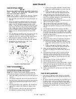
Page 7: ...asher for damage and replace as required 6 Clean the shaft portion protruding through the head thoroughly making sure the shaft is free of nicks and burrs This will prevent damage to the mechanical se...

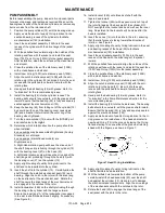
Page 8: ...the seal jacket of the mechanical seal Rotate the shaft to ensure the drive tangs of the mechanical seal are engaged in the notches in the rotor 15 Install lockwasher 24B on the shaft protruding thro...

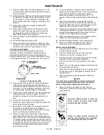
Page 9: ...B Tighten just past the desired tang then back off the nut to align the tang with the locknut slot Secure the nut by bending the aligned lockwasher tang into the slot in the locknut The pump should co...

Page 10: ...ended periods with a closed discharge line 3 Pump not securely mounted 4 Misalignment of pump or motor base mounted pumps 5 Bearings worn or damaged 6 Vibration from improperly anchored piping 7 Bent...

Page 11: ...101 A00 Page 11 12 NOTES...

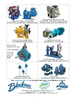
Page 12: ...215 GPM HXL 6 8 10 Sliding Vane Pumps 130 to 2 220 GPM Refineries Terminals Barges Ships Reciprocating Gas Compressors Liquefied Gas Transfer Boosting Vapor Recovery Hand Operated Pumps Dispensing Tra...

Reviews: