104-A00 Page 12/16
MAINTENANCE
Hazardous
machinery can
cause serious
personal injury.
Failure to stop the pump before
adjusting the shaft packing can cause
severe personal injury.
9.
PACKING ADJUSTMENT
Packing must be properly adjusted to prevent overheating.
a. While the liquid is being pumped, check for leakage
from the stuffing box. STOP the pump and uniformly
tighten the packing follower stud nuts (18) 1/4 turn at
a time to reduce leakage.
b. Restart the pump and check the stuffing box
temperature several minutes after each adjustment
for signs of overheating.
c.
Check the packing again after 20-30 minutes of
running the pump, and readjust if necessary.
NOTE:
Some leakage is desirable to lubricate the
packing, but in some cases is unacceptable,
depending on the application.
10. BLACKMER TRIPLE-LIP SEAL (if equipped)
On pumps equipped with a Blackmer triple-lip seal, refer to the
separate literature accompanying the triple-lip seal for
installation instructions.
11. COMMERCIAL MECHANICAL SEAL (if equipped)
On pumps equipped with a commercial mechanical seal, refer
to the separate literature accompanying the mechanical seal
for installation instructions.
12. SHAFT SUPPORT BEARING (SNP3A if equipped)
a. Screw the short threaded ends of the two hex studs
(106E) firmly into the holes in the head.
b. Place the bearing flange (106) on the studs and tighten
the locknuts (106A).
c. Slide the bearing and lock collar (106B) on the shaft
until it is firmly seated in the bearing flange (106A).
d. Push inward on the bearing and lock collar (106B)
while turning the lock collar by hand in the same
direction as the shaft rotation.
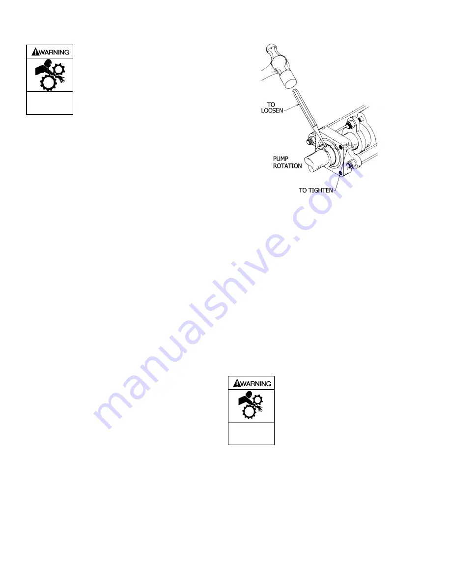
e. Lock the collar to the shaft with a punch in the same
direction as the shaft rotation. See Fig. 11.
f. Bolt on the flange cover (106C).
g. If the shaft does not turn freely, loosen the lock collar
and make sure the bearing is firmly seated in the
bearing flange (106). Re-tighten the lock collar.
Figure 11 – Shaft Support Bearing Lock Collar
13. RELIEF VALVE ASSEMBLY (if equipped)
a. Insert the valve (9) into the relief valve body (6) with
the fluted end inward.
b. Install the relief valve spring (8) and spring guide (7)
against the valve.
c.
Attach a new relief valve gasket (10) and the valve
cover (4) on the relief valve body (6).
d. Screw the relief valve adjusting screw (2) into the
valve cover until it makes contact with the spring
guide (7).
e. Install the relief valve cap (1) and gasket (88) after
the relief valve has been precisely adjusted.
NOTICE:
The relief valve setting MUST be tested and
adjusted more precisely before putting the pump
into service. Refer to "Relief Valve Setting and
Adjustment"
14. Reinstall coupling, shaft key, and coupling guards.
Do not operate
without guard in
place.
Operation without guards in place can
cause serious personal injury, major
property damage, or death.
15. Refer to “Pre-Start Up Check List” and “Start Up
Procedures” sections of this manual prior to pump
operation.
Summary of Contents for SNP1.25
Page 15: ...104 A00 Page 15 16 NOTES...


