103-A00 page 5/12
OPERATION
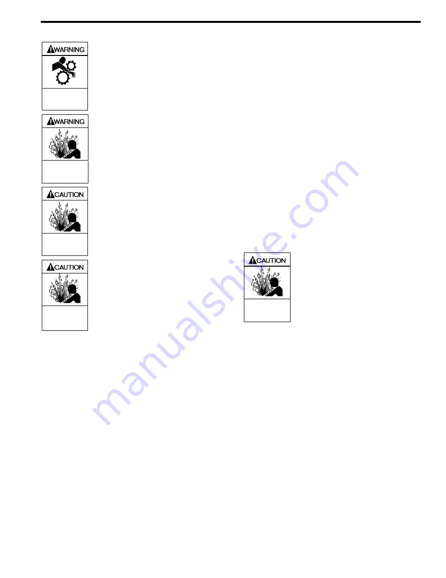
Operation without guards in place can
cause serious personal injury, major
property damage, or death.
Do not operate
without guard
in place
Disconnecting fluid or pressure
containment components during pump
operation can cause serious personal
injury, death or major property damage
Hazardous pressure
can cause personal
injury or property
damage
Failure to relieve system pressure prior
to performing pump service or
maintenance can cause personal injury
or property damage.
Hazardous pressure
can cause personal
injury or property
damage
Pumps operating against a closed valve
can cause system failure, personal
injury and property damage
Hazardous pressure
can cause personal
injury or property
damage
PRE-START UP CHECK LIST
1. Check the alignment of the pipes to the pump. Pipes
should be supported so that they do not spring away or
drop down when pump flanges or union joints are
disconnected.
2. Verify proper coupling alignment.
3. If equipped with a gear reducer, check the oil level in the
gear reducer. Fill with the grade of oil indicated on the
reducer tag. For more specific instructions on Blackmer
gear reducers, refer to the appropriate Gear reducer
Installation, Operation and Instruction Manual.
NOTICE:
Blackmer gear reducers are not lubricated at the factory.
Oil must be added before initial pump start up.
4. Check the entire pumping system to verify that the proper
inlet and discharge valves are fully open, and that the
drain valves and other auxiliary valves are closed.
5. Install vacuum and pressure gauges on the pump in the
1/4” NPT connections provided to check suction and
discharge conditions after pump start-up.
6. Check the wiring of the motor, and briefly turn on the
power to make sure that the pump rotates in the direction
of the rotation arrow.
START UP PROCEDURES
NOTICE:
Consult the "General Pump Troubleshooting" section of
this manual if difficulties during start up are
experienced.
1. Start the pump. Priming should occur within one minute.
2. Check the vacuum and pressure gauges to see if the
pump is operating within the expected conditions.
Record the readings in the ‘Initial Start Up Information’
section of this manual for future reference.
3. Inspect piping, fittings, and associated system
equipment for leaks, noise, vibration and overheating.
4. If possible, check the flow rate. Record the readings in
the ‘Initial Start Up Information’ section of this manual
for future reference.
5. Check the pressure setting of the relief valve by briefly
closing a valve in the discharge line and reading the
pressure gauge. This pressure should be 10-20 psi
(0.7-1.4 bar) higher than the maximum operating
pressure, or the external bypass valve setting (if
equipped).
DO NOT operate the pump against a
closed discharge valve for more than 15 seconds.
If
adjustments need to be made, refer to "Relief Valve
Setting & Adjustment."
Incorrect settings of the pressure relief
valve can cause pump component
failure, personal injury, and property
damage.
Hazardous pressure
can cause personal
injury or property
damage
RUNNING THE PUMP IN REVERSE
ROTATION
NOTICE:
The pump should be operated in reverse rotation for no
more than 10 minutes and only when a separate
pressure relief valve is installed to protect the pump
from excessive pressure.
It may be desirable to run the pump in reverse rotation for
system maintenance. The pump will operate satisfactorily in
reverse rotation for a LIMITED time,
at a reduced
performance level.


