


701-B00 page 6/12
INSTALLATION
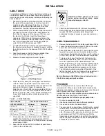
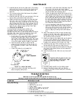
5. The yokes of the universals at both ends of the jack
shaft must be parallel and in phase.
6. The maximum recommended angle between the jack
shaft and the pump shaft is 15 degrees. See Table 1.
Failure to follow any of these guidelines may result in a
gallop or uneven turning of the pump rotor, which will in turn
cause a surging vibration to the liquid stream and piping
system. Contact the supplier of the drive line components for
specific design assistance.
PTO driven units MUST contain speed control devices to
prevent pump speeds above the maximum RPM
specifications, regardless of the truck engine unloading
speeds. Should fluid delivery be appreciably less than
expected, see the "General Pump Troubleshooting" section.
Do not operate
without guard
in place
A drive shaft guard between the pto
and pump must be provided to prevent
personal injury, property damage, or
death.
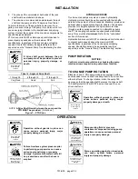
Tabel 2 - Angle of Drive Shaft
1
o
through 5
o
6
o
through 10
o
11
o
through 15
o
Very Good
Good
Fair
NOTE:
A Drive Shaft Guard between the pump and the
PTO MUST be provided.
(Not shown)
Figure 7 – PTO Drive
HYDRAULIC DRIVE
Truck mounted pumps may also be driven hydraulically.
Hydraulic motors should be well supported with their shafts
parallel to the pump shaft in all respects. Blackmer provides an
optional close-coupled hydraulic motor adapter. The adapter
provides for straight alignment of a hydraulic motor drive
through a solid coupling connected to a straight key pump
shaft. This coupling connection requires grease lubrication
every three months at
minimum
. Refer to the "Lubrication"
section of this manual.
Hydraulically driven units MUST contain speed control devices
to prevent pump speeds above the maximum RPM
specifications, regardless of the truck engine unloading
speeds. Should fluid delivery be appreciably less than
expected, see the "General Pump Troubleshooting" section.
PUMP ROTATION
NOTICE:
Confirm correct pump rotation by checking the pump
rotation arrows respective to pump driver rotation.
TO CHANGE PUMP ROTATION
Blackmer 2 and 3” CRL pump models are equipped with a
double ended rotor and shaft, enabling them to be driven from
either shaft end. To change rotation, rotate the pump 180
degrees so that the opposite shaft becomes the driven shaft.
The shaft protector (186) MUST be mounted over the non-
driven shaft end.
Do not operate
without guard
in place
Operation without guards in place can
cause serious personal injury, major
property damage, or death.
OPERATION
Do not operate
without guard
in place
Operation without guards in place can
cause serious personal injury, major
property damage, or death.
Hazardous pressure
can cause serious
personal injury or
property damage
Failure to relieve system pressure prior
to performing pump service can cause
serious personal injury or property
damage.
Systems with meters will still
be pressurized even after the hose is
emptied
Hazardous pressure
can cause serious
personal injury or
property damage
Disconnecting fluid or pressure
containment components during pump
operation can cause serious personal
injury or property damage.
Hazardous pressure
can cause personal
injury or property
damage
Pumps operating against a closed valve
can cause system failure, personal
injury and property damage


