


701-B00 page 5/12
INSTALLATION
V-BELT DRIVE
For installation of Blackmer V-belt units, first mount the pump
and the motor base to the unit base. Do not fully tighten the
motor mounting bolts until properly installing and adjusting the
belts as follows:
1. Wipe the cone surface of the pump QD hub (152A) and
the inside of the pump sheave hub with a clean cloth
moistened with a light grade of machine oil. This will
allow for a more uniform draw and prevent the cone
surfaces from “freezing” before being tightened.
2. With the pump shaft key (35) in place, align the key seat
and slide the QD hub (152A) on the shaft, flange end
first. Slide the large end of the sheave (152) bore over
the taper on the QD hub. Insert the three sheave
capscrews (152G) through the clearance holes in the
sheave, and start them into the tapped holes of the QD
hub (152A). Repeat this procedure to assemble the
motor QD hub (152E) and sheave (152D).
3. To install the belts (181), shorten the center distance of
the drive by moving the motor towards the pump, until the
the belts can be put on the sheaves (152 & 152D) without
forcing.
4. Align the sheaves so that the faces are parallel, then
snug up the sheave capscrews (152C & G).
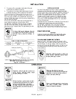
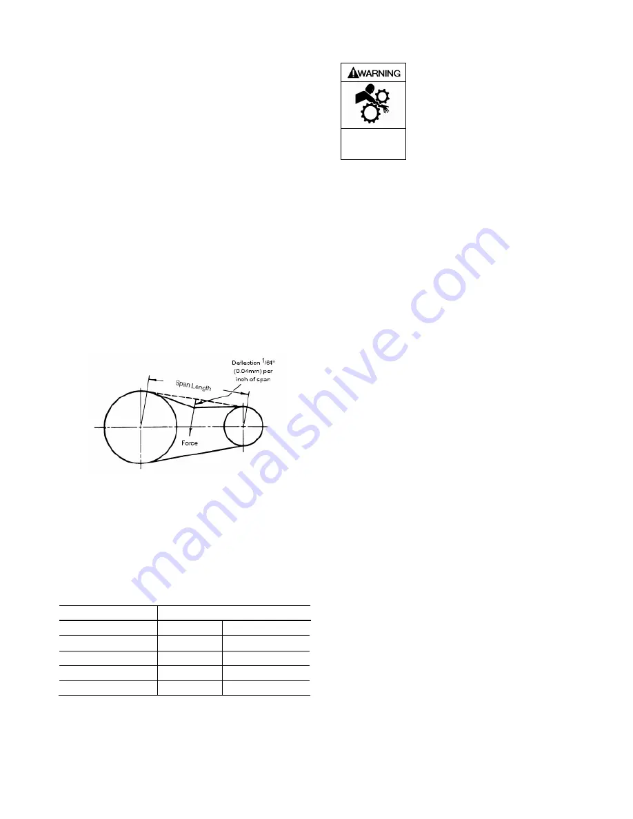
5. Measure the span length as shown in Figure 6.
Figure 6 – V-Belt Adjustment
6. Adjust the motor base (183) and apply a specified force
(refer to Table 1) against the belt, at the center of the
span, so that the belt is deflected 1/64 inch (0.04 mm) for
every inch (25.4 mm) of span. For example, the
deflection of a 20 inch (508 mm) span would be 20/64 or
5/16 inch (7.9 mm). The force required should be within
the range given in Table 1 for a properly tensioned drive.
A new set of belts should be initially tensioned to the
upper limit.
Table 1 – V-Belt Deflection
SMALL SHEAVE
BELT DEFLECTION FORCE
OUTSIDE DIAMETER
Minimum
Maximum
2.5
" to
4.5
"
3.0 lbs.
4.75 lbs.
(63.5 mm to 114.3 mm)
(1.4 kgs.)
(2.2 kgs.)
4.75
" to
7.0
"
4.0 lbs.
6.0 lbs.
(120.7 mm to 177.8 mm)
(1.8 kgs.)
(2.7 kgs.)
7. Check again to ensure the sheaves (152 & 152D) are
parallel, then tighten the sheave capscrews (152C &
152G), the motor mounting nuts (183B) and the adjusting
screw locknut (183B).
8. Assemble the belt guard (182) and the belt guard brace
(182A) to the unit base (32).
Do not operate
without guard
in place
Operation without guards in place can
cause serious personal injury, major
property damage, or death.
9. Check the belt tension after 24-48 hours of operating.
Recheck the tension periodically and tighten the belts as
required. DO NOT overtighten belts. Inspect belts
periodically for signs of excessive wear, and replace as
required.
V-BELT DISASSEMBLY
1. Remove the belt guard (182) and the guard base (182A).
2. Loosen the adjusting screw locknut (183B) on the motor
base (183) and the motor mounting nuts.
3. Ease the tension on the belts (181) by moving the motor
towards the pump to shorten the center distance of the
drive. Remove the belts by sliding them over the sheaves
(152 & 152D). DO NOT force the belts over the grooves.
4. To remove the sheave from the hub, first remove the
three sheave capscrews (152C or 152G). Then screw
two of the capscrews into the threaded holes in the
sheave hub (152A or E). If the cone grip is hard to break
loose, tap the end of the shaft or the QD hub with soft-
faced mallet while maintaining pressure on the screw.
5. The QD hub should slide smoothly off the shaft. If it is
tight on the shaft, gently pry it loose with a screwdriver or
a small wedge placed in the split part of the flange.
Refer to Blackmer V-Belt Parts List and Instructions for
V-belt drive and guard part numbers.
PTO DRIVE
The pump may be driven by a power take-off through
universal joints. When using universal joints, a splined slip
joint, properly lubricated, must be used on the connecting jack
shaft to prevent end thrust on the pump shaft.
A proper drive line must be installed to avoid excessive wear,
vibration and noise (see Figure 7 and Table 2).
General guidelines to follow for proper pump drive:
1. Do not use square slip joints.
2. Use the least number of jack shafts as is practical.
3. Use an even number of universal joints.
4. The pump shaft and power take-off shaft must be parallel
in all respects. Use an angular level measuring device to
ensure the PTO and pump shaft are parallel to each
other. If necessary, the pump can be shimmed to correct
any misalignment. The PTO shaft coming off at the
transmission does not need to be perfectly horizontal as
long as the pump is shimmed to have its shaft parallel in
all respects to the PTO shaft.


