background image

17

 High Performance 690 TVL CCTV Dome Camera User Manual

SECTION 3: SOFTWARE SETUP

Rock the joystick to DOWN to highlight the POSITION line. Rock the joystick to LEFT or RIGHT to change the position option. 
Options include: 


UP-LEFT / UP-CENTER / UP-RIGHT / DOWN-LEFT / DOWN-RIGHT 

3.7.2  VIDEO I/O

The VIDEO I/O submenu offers several options including VIDEO STANDARD, VIDEO OUT, DIGITAL OUT, 656 OSD, and FIELD ORDER. The 
VIDEO OUT, DIGITAL OUT, 656 OSD, and FIELD ORDER adjustments are for factory use only and should not be changed. 

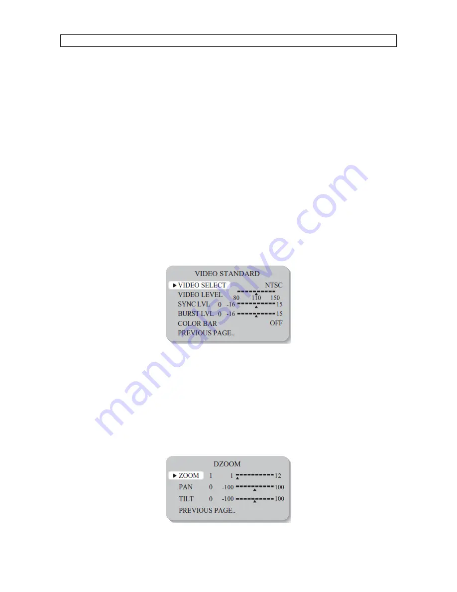
VIDEO STANDARD

The VIDEO STANDARD submenu is used to setup the video signal transmitted to the monitoring equipment. Options:

• 

VIDEO SELECT : NTSC / PAL. This option must remain as NTSC. Do not change this option. 

• 

VIDEO LEVEL / SYNC LVL / BURST LVL : Change these settings as necessary to produce the optimal video signal transmitted to 
the monitoring equipment. These levels are set at the factory and usually do not need adjustment. 

• 

COLOR BAR : ON / OFF : Turns color bars on or off for use during video signal adjustments. 

3.7.3  DZOOM

Digital P/T/Z are used to create a zoom lens effect. Options: 

• 

ON : Use the DZOOM feature. Selecting ON opens the DZOOM submenu


Zoom factor (1x to 8x). To use Pan and Tilt, the zoom factor must be greater than 1x. 


Pan factor (±100%, center of image can be moved to left and right edges of screen)


Tilt factor (±100%, center of image can be moved to top and bottom edges of screen)

• 

OFF : DZOOM is not in use. 

Summary of Contents for BLK-CWD208VH2

Page 1: ...V Dome Camera User Manual Products BLK CWD208VH2 BLK CWD228VH2 Please read this manual before using your camera and always follow the instructions for safety and proper use Save this manual for future...

Page 2: ...own expense LEGAL NOTICE Observint Technologies Observint products are designed to meet safety and performance standards with the use of specific Observint authorized accessories Observint disclaims l...

Page 3: ...General Guidelines 4 2 2 Vandalproof camera mounting 5 2 3 Plastic camera mounting 6 2 4 Camera adjustments 6 2 5 Cleaning 7 SECTION 3 Software Setup 8 3 1 PRESETS 8 3 2 EXPOSURE 8 3 3 WDR 11 3 4 WHI...

Page 4: ...flicker can cause the camera to work improperly Never use the camera close to a gas or oil leak These chemicals can damage the camera Do not drop the camera or subject it to physical shocks These can...

Page 5: ...ng mounting through 3 axis camera bracket Vandalproof enclosures are IP67 rated and constructed with die cast aluminum Flush surface mountable using the supplied mount adaptor Safety strap keeps dome...

Page 6: ...Gimbal tilt lock LensControls 1 1 Cameras with a vandalproof enclosure 1 1 1 What s in the box Your camera includes the following Security tool Machine screws 4 Mounting cap Mounting screws 4 L wrenc...

Page 7: ...CTION 1 INTRODUCTION Optionaldomebracketforwallandceilingmounting 1 2 Cameras with a plastic enclosure 1 2 1 What s in the box Your camera includes the following Mounting screws 4 L wrench User manual...

Page 8: ...f view CAUTION Keepdome coverandcameralens clean Toavoidsmearing donotexposethecameralensto astronglightsourcesuchasthe sunor spotlights Monitor impedance Set the monitor impedance switch to 75 Power...

Page 9: ...a can be installed on a junction box or directly to a wall or ceiling 1 Attach the surface mount bracket to the ceiling or wall using four 4 mounting screws 2 Connect the dome base to the surface moun...

Page 10: ...e General guidelines above 2 4 Camera adjustments 1 Attach a video setup monitor to the yellow RCA EXTRA VIDEO OUT connector inside the camera assembly or setup a remote monitor for viewing video from...

Page 11: ...g Clean the camera dome with an approved glass cleaning solution and a lint free cloth Dust can be removed from the unit by wiping it with a soft damp cloth To remove stains gently rub the surface wit...

Page 12: ...t and left or right display the option you want to select The SETUP menu consists of a list of sub menus or displays the option selected for a camera function When sub menus are available the symbol i...

Page 13: ...PREVIOUS PAGE 3 2 2 FOCUS Use the FOCUS submenu to sharpen the camera focus and select the focus region With the lens pointed at the surveillance target the camera will set the focus based on the focu...

Page 14: ...0i 30p 3 2 4 AGC AGC Automatic Gain Control is used to automatically adjust the brightness A higher AGC setting compensates for darker environments but produces more noise in the image Options LOW MID...

Page 15: ...ps to maintain a clear image in dark lighting conditions Options 2X 4X 8X 16X 32X OFF Deactivates the SENS UP function 3 3 WDR WDR Wide Dynamic Range function brightens dark areas in images with large...

Page 16: ...rature is between 2000 K 11000 K AWB To automatically set the white balance for the current luminance levels point the camera at a sheet of white paper and press the Joystick down toward the PC board...

Page 17: ...where illumination changes significantly thewhitebalancemaybecomeunstable Inthese environments selectAWBmode 3 5 DAY NIGHT The DAY NIGHT feature controls how the camera switches modes for different li...

Page 18: ...IMAGE ADJ Select IMAGE ADJ to open the IMAGE submenu 3 6 1 FREEZE Freeze creates a still image of the screen Options OFF ON 3 6 2 FLIP Flip allows you to reverse the image horizontally vertically or b...

Page 19: ...distinct as the level of SHARPNESS setting increases If the SHARPNESS is set too high noise may appear Adjustment range 8 8 3 6 4 COLOR GAIN Used to control the color level in the image Adjustment ra...

Page 20: ...ions OFF Camera ID is not displayed ON Camera ID is displayed After selecting ON the camera ID submenu opens To set the camera ID name highlight the ID row then press SET The first character in the na...

Page 21: ...he monitoring equipment Options VIDEO SELECT NTSC PAL This option must remain as NTSC Do not change this option VIDEO LEVEL SYNC LVL BURST LVL Change these settings as necessary to produce the optimal...

Page 22: ...appears on the image when motion is detected SETUP MOTION ZONE Select this option to select the area of the image to monitor for motion 1 When the rectangle is white rock the joystick UP DOWN LEFT and...

Page 23: ...rd to open the mask position window In the position window rock the joystick to UP DOWN LEFT or RIGHT to move the mask position up down right or left When the mask covers an area you want to block pre...

Page 24: ...to synchronize the video signal between cameras through adjusting the video phase of the camera signal After the phase is adjusted press the joystick down toward the PC board to save the setting 3 7...

Page 25: ...in Illumination 0 1 lux Color 0 01 lux B W Day Night Auto Color B W White Balance Auto AWB Indoor Outdoor Manual WB Range 2000 K 11 000 K Shutter Speed up to 1 30 720 s Sens up Auto Off selectable x2...

Page 26: ...nsitivity set too low Increase the sensitivity Check the setting of the MD AREA The WDR function is not working Is the WDR level too low Is the AE Mode set to MANUAL WDR is disabled in MANUAL exposure...

Page 27: ...ormance 690 TVL CCTV Dome Camera User Manual APPENDIX B CAMERA DIMENSIONS APPENDIX B Camera Dimensions Camera with vandalproof housing 4 96 2 95 1 38 2 95 1 61 Camera with plastic housing 2 09 3 29 1...

Reviews: