background image

14

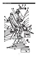
REF#

PART#

DESCRIPTION

QTY

1

T830021Q.3

Power unit assembly

1

2

T83508.3.1(asm)

Universal joint assembly

1

3

GB308-6

Steel ball bearing Ø6mm

1

4

TF1201C-29

Oil plug

1

5

Return spring

2

6

Cotter pin Ø4X40mm

1

7

Coupling connector

1

8

C-clip Ø30mm

2

9

Lifting arm assembly

1

10

Supporting shaft

1

11

GB894.1-25

C-clip Ø25mm

2

12

T830018ZH.5-1(ASM)

Height adjustment extension saddle

1

13

T830018ZH.5-3(ASM)

Post for extension saddle

1

14

T830018ZH.5.1

Pin for post

2

15

GB894.1-16

C-clip Ø16mm

2

16

Connecting rod pintle

2

17

T84004-3

Front wheel

2

18

GB894.1-18

C-clip Ø18mm

1

19

Frame assembly

2

20

Washer M16

2

21

GB859-16

Spring washer M16

2

22

Nut M16

2

23

GB859-6

Spring washer M6

2

24

GB67-M6X10

Pan head combination drive machine screw M6x10mm

4

25

Spring washer M12

2

26

Socket head cap screw M12X25mm

2

27

GB6170-M16

Nut M16

1

28

T83508.6(ASM)

Rear caster assembly

2

29

Back shaft

2

30

Nut M12

2

31

Shoulder bolt M18X54mm

2

32

Spring washer M18

1

33

Washer M18

2

34

Pin for roller

2

35

Pan head combination drive machine screw M8X10mm

2

36

Spring washer M8

1

37

T84004-7

Rubber set

1

38

Handle socket shaft

1

39

T830018ZH.2

Cover plate

1

40

Handle socket

1

41

QLZ2C-1a

Handle socket screw M10X19mm

1

42

GB894.1-10

C-clip Ø10mm

1

43

Contact roller

1

44

T830018Z.2

Handle assembly

1

45

T83508.5-4

Handle lock pin

1

46

QLZ2C.2-4

Handle cover

47

T830018ZH.4

Saddle

48

T830021Q.MF

Seal kit

49

T815012L.1-6

Flexible protective pipe

Summary of Contents for T830018ZH

Page 1: ...etailer call our customer service department at 1 888 44 TORIN 1 888 448 6746 8 a m 5 p m PST Monday Friday Read carefully and understand all ASSEMBLY AND OPERATION INSTRUCTIONS before operating Failu...

Page 2: ...for any application other than that for which this product was designed If you have any questions relative to a particular application DO NOT use the product until you have first contacted the distrib...

Page 3: ...se instructions Inspect the service jack for proper operation and function Keep instructions readily available for equipment operators Make certain all equipment operators are properly trained underst...

Page 4: ...ehicle while on the jack 6 Lift only on areas of the vehicle as specified by the vehicle manufacturer 7 No alterations shall be made to this product 8 Only attachments and or adapters supplied by the...

Page 5: ...nd block stabilize the load to be lifted Never place any part of the body under a raised load without properly chocking and supporting the load Never use the jack on curved or tubular vehicle Bumpers...

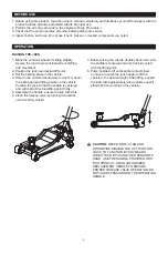
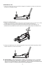
Page 6: ...NG 4 Unfasten the screw located in the Handle Socket to insert the assembled handle 5 Line up the square hole located at the bottom of the handle over the square bolt inside the Handle Socket 6 Secure...

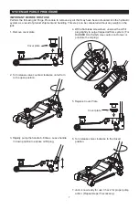
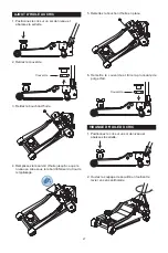
Page 7: ...lockwise on full turn to the open position 4 With a flat blade screwdriver unscrew the oil fill plug slightly to purge trapped air from system For RUBBER OIL PLUGS Use caution not to tear or puncture...

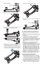
Page 8: ...THE OPERATING HANDLE 1 Block the vehicle s wheels for lifting stability Secure the load to prevent inadvertent shifting and movement 2 Position the jack near desired lift point 3 Set the parking brak...

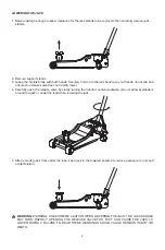
Page 9: ...Carefully open the release valve by slowly turning the handle counter clockwise Do not allow bystanders around the jack or under the load when lowering the jack WARNING WARNING USE EXTREME CAUTION WH...

Page 10: ...nt using light penetrating oil lubricating spray Use a good lubricant on all moving parts For light duty use lubrication once a month For heavy and constant use lubrication recommended every week NEVE...

Page 11: ...evel ground and lower the saddle 3 Remove the oil plug 4 Fill the oil case until oil level is just beneath the lower rim of the oil fill hole 5 Replace oil plug 2 Open release valve by turning handle...

Page 12: ...SS OF LOAD DISPOSE OF HYDRAULIC FLUID IN ACCORDANCE WITH LOCAL REGULATIONS ADDITIONAL LUBRICATION 1 Periodically check the pump piston and ram for signs of rust or corrosion Wipe as needed with a clea...

Page 13: ...13 ASSEMBLY DIAGRAM...

Page 14: ...16 Spring washer M16 2 22 Nut M16 2 23 GB859 6 Spring washer M6 2 24 GB67 M6X10 Pan head combination drive machine screw M6x10mm 4 25 Spring washer M12 2 26 Socket head cap screw M12X25mm 2 27 GB6170...

Page 15: ...ems listed with a Part are available for purchase For assistance with the operation or the availability of replacement parts contact our Parts and Warranty Department at 1 888 44 TORIN 1 888 448 6746...

Page 16: ...stributor does not have authorization to amend these statements You acknowledge and agree that any modification of the product for any purpose other than manufacturer completed repairs is at your own...

Page 17: ...ur appelez notre service la client le au 1 888 44 TORIN 1 888 448 6746 entre 8 heures et 17 heures HNP du lundi au vendredi Lisez attentivement et comprenez toutes les DIRECTIVES DE MONTAGE ET DE FONC...

Page 18: ...es pi ces de rechange autoris es ou approuv es la n gligence rendra l utilisation du produit dangereuse et annulera la garantie Inspectez r guli rement et avec soin le produit et effectuez tout l entr...

Page 19: ...n bon tat et bien lubrifi peut provoquer des blessures graves Inspectez l aire de travail avant chaque utilisation Assurez vous qu elle est libre de tous dangers potentiels NE PAS UTILISER OU R PARER...

Page 20: ...cric 6 Soulevez un v hicule en ces seuls points sp cifi s par le constructeur du v hicule 7 Aucunes modifications ne doivent tre apport es ce produit 8 Seules les fixations ou adaptateurs fournis par...

Page 21: ...ort Calez ou bloquez stabilisez toujours de mani re s curitaire la charge soulever Ne placez jamais une partie du corps sous une charge soulev e sans avoir cal et support ad quatement la charge N util...

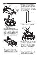
Page 22: ...r alisation de cette op ration Activer la d connexion rapide sur la pi ce 2 du levier cela vous permettra de connecter les pi ces glissantes 1 et 2 du levier alignez les trous sur les deux sections af...

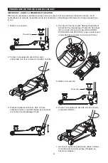
Page 23: ...3 Pompez rapidement le levier de 6 8 fois Laissez le levier en position basse pour exposer le bouchon de remplissage d huile 4 l aide d un tournevis plat d vissez l g rement le bouchon de remplissage...

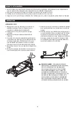
Page 24: ...ionnez le cric pour que la sellette soit centr e et entre en contact fermement avec le point de levage de la charge 5 Assemblez le levier en vous assurant d aligner les fentes 6 Fermez la soupape de s...

Page 25: ...de s curit en tournant lentement le levier en sens antihoraire Ne permettez pas aux spectateurs de se tenir autour du cric ou sous la charge lorsque vous abaissez le cric 5 Lorsque vous n utilisez pas...

Page 26: ...e l g re ou d une vaporisation d huile Utilisez un bon lubrifiant sur toutes les pi ces mobiles Dans le cas d un usage l ger il faut lubrifier une fois par mois Dans le cas d un usage constant et inte...

Page 27: ...niveau se situe sous le rebord inf rieur du trou de remplissage 5 Remettez le bouchon d huile en place VIDANGE D HUILE DU CRIC 1 Positionnez le cric sur un sol de niveau et abaissez la sellette 2 Ouvr...

Page 28: ...GER DIFF RENTS TYPES DE LIQUIDES ET N UTILISEZ JAMAIS DE LIQUIDE DE FREIN D HUILE POUR TURBINE D HUILE DE TRANSMISSION D HUILE MOTEUR OU DE GLYC RINE UN LIQUIDE INAPPROPRI PEUT PROVOQUER LA D FAILLANC...

Page 29: ...29 SCH MA DE MONTAGE...

Page 30: ...e lastique M16 2 22 crou M16 2 23 GB859 6 Rondelle lastique M6 2 24 GB67 M6X10 Vis de m canique pouss e combin e t te cylindrique M6x10mm 4 25 Rondelle lastique M12 2 26 Vis d assemblage six pans creu...

Page 31: ...commandations Seuls ces articles num r s l aide d un num ro de pi ce sont disponibles pour achat Pour obtenir de l aide quant au fonctionnement ou la disponibilit des pi ces de rechange communiquez av...

Page 32: ...ue toute modification du produit dans un but autre que les r parations effectu es par le fabricant se fait vos propres risques Avant d utiliser ce produit lisez enti rement le manuel du propri taire e...

Page 33: ...0am 5 00pm Pacific Time Monday Friday Communiquez directement avec le Service la client le Torin au 1 888 44 TORIN 1 888 448 6746 De 8 heures 17 heures heure du Pacifique du lundi au vendredi Torin In...

Reviews: