If the data rate is less than you expect (e.g. a 100 MB/s communi-
cating at 10 MB/s), look for one of these problems:
●
The LAN device is a 10 Base-T port only.
●
There is a “Cable Fault.” A cable fault is when a wiring pair is
inverted.
●
The LAN ports is initialized to 10 MB/s (e.g. the PC was
booted while not connected to the 100 MB/s LAN). Some
PCs will only boot up to 100 MB/s if they detect a 100
MB/s connection. Perform an inline test between the two devices
(see example #2 below).
Test example #2.
Connecting a PC to a Switch (using the
INLINE
MODE).
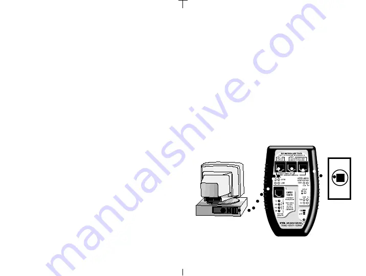
The TVR1000 can be inserted in between two
LAN devices without disrupting LAN communications. Because the
TVR1000 can display the device type and speed/duplex of both
devices plus simulate a straight thru or crossover cable connection,
it helps you to quickly sort out problems. In this example, the Main
Unit will 1) test if if one LAN device is slowing down the other and 2)
see what patch cable (straight thru or crossover) is required to make
the correct connection. The TVR1000 lets the two devices negotiate
to determine their own speed and duplex.
Equipment required: TVR1000 Main Unit and two straight thru RJ45
patch cables.
Step 1:
Turn ON tester.
Step 2. Make the connections:
Plug a straight thru patch cable
(provided) between the GREEN JACK and the wall plug that
connects to the switch. Use the other straight thru patch cable to
connect the middle jack of the TVR1000 to the LAN port on the PC
(the middle jack is a straight thru connection to the GREEN JACK).
A straight thru connection now exists between the switch and the
PC (assuming no crossover cables).
After turning on the tester,
24
allow a minimum of 3 seconds between connections (this is the time
it takes the TVR1000 to make a reading).
Step 3. Get them communicating:
Study the “DATA” and"LINK"
LEDs. If communicating, a LED will be ON in both columns (“HUB”
and “PC”). If not, switch the cable in the middle jack to the rightmost
jack (rightmost jack is a crossover connection to the GREEN JACK).
For this example we will presume that the straight-thru connection
allowed communication (so we don't need to worry about adding a
crossover cable to our network).
Step 4. SPEED/DUPLEX test:
If all is well, a Speed Verification LED
will be ON for each device (one for the switch and one for the PC).
This is the
negotiated
speed and duplex of the two devices.
Step 5. Am I slower?:
Study the Speed Verification LEDs and see if
Using 2 leftmost sockets simulates a
straight thru connection
PC or hub/switch
Straight thru patch cables
(included)
Wall socket
to switch
Test example #2
Two devices tested
using the
inline
mode
25
Summary of Contents for TS029A-R4
Page 1: ......


