background image

23

CHAPTER 5: Operation

5. Operation

NOTE

We recommend that the first time you start up your Caller ID system,
you test it as described in 

Section 6.1

.

5.1 LEDs

There are two LEDs on the front panel of each Caller ID unit. One is the Power
LED, which lights as soon as the unit starts receiving power. The other is the DATA
LED, which flashes to show that data is being sent from the Caller ID unit to the
DTE. (A unit won’t light its DATA LED unless it’s connected to a powered DTE—
specifically, it needs to receive Pin 7, RTS, active/high on its RS-232 OUT port.)

5.2 How the Unit Handles Caller ID Information

The Caller ID unit receives standard Caller ID information from the telephone
company’s central office as Bell

®

202A modem tones, between the first and second

rings of the phone call. The Caller ID unit takes this information, formats it as an
ASCII text record (as shown in Figure 5-1), prefaces it with the number of the port
on which the call was received, and sends it from its RS-232 OUT port to the DTE.

NOTE

If handshaking between the Caller ID system and the DTE is prolonged,
data could be lost.

Figure 5-1. Sample Caller ID records produced by the Caller ID unit 

(not actual width—filler spaces compressed).

LINE DATE   TIME    PHONE NUMBER  L      NAME*

08  3/24  9:15 AM    OUT OF AREA

01  3/24  9:16 AM 1-724-555-3407          Jane Doe

12  3/24 10:03 AM 1-205-555-4000 L      John Smith

03  3/24 10:03 AM        PRIVATE

10  3/24 10:06 AM       555-9818   Bednarski Motor

03  3/24  8:00 PM       555-2549         Sam Jones

*Labels are shown here at the tops of the columns for clarity only. 

No such labels are sent to the DTE.

Summary of Contents for TE120A

Page 1: ... call 724 746 5500 FREE technical support 24 hours a day 7 days a week Call 724 746 5500 or fax 724 746 0746 Mailing address Black Box Corporation 1000 Park Drive Lawrence PA 15055 1018 Web site www blackbox com E mail info blackbox com OCTOBER 2001 TE120A TE121A 4 and 8 Line Caller ID ...

Page 2: ...e the user at his own expense will be required to take whatever measures may be necessary to correct the interference Changes or modifications not expressly approved by the party responsible for compliance could void the user s authority to operate the equipment This digital apparatus does not exceed the Class A limits for radio noise emission from digital apparatus set out in the Radio Interferen...

Page 3: ...he problem If it is contact Black Box or an authorized agent 4 The telephone company may make changes in its technical operations and procedures If any such changes affect the compatibility or use of this device the telephone company is required to give adequate notice of the changes 5 If the telephone company requests information on what equipment is connected to their lines inform them of a The ...

Page 4: ...uipment should be made by an authorized Canadian maintenance facility in this case Black Box Any repairs or alterations made by the user to this equipment or equipment malfunctions may give the telecommunications company cause to request the user to disconnect the equipment Users should ensure for their own protection that the electrical ground connections of the power utility telephone lines and ...

Page 5: ...aparato eléctrico debe ser montado a la pared o al techo sólo como sea recomendado por el fabricante 8 Servicio El usuario no debe intentar dar servicio al equipo eléctrico más allá a lo descrito en las instrucciones de operación Todo otro servicio deberá ser referido a personal de servicio calificado 9 El aparato eléctrico debe ser situado de tal manera que su posición no interfiera su uso La col...

Page 6: ...r una antena externa deberá ser localizada lejos de las lineas de energia 16 El cable de corriente deberá ser desconectado del cuando el equipo no sea usado por un largo periodo de tiempo 17 Cuidado debe ser tomado de tal manera que objectos liquidos no sean derramados sobre la cubierta u orificios de ventilación 18 Servicio por personal calificado deberá ser provisto cuando A El cable de poder o ...

Page 7: ...he Complete Package 17 3 Configuration 18 3 1 DIP Switch S1 TE121A Only 18 3 2 DIP Switch S2 19 4 Installation 20 5 Operation 23 5 1 LEDs 23 5 2 How the Unit Handles Caller ID Information 23 5 3 Message Format 24 6 Troubleshooting 25 6 1 Testing 25 6 2 Things to Try 25 6 3 Calling Black Box 26 6 4 Shipping and Packaging 26 Appendix Wallmount Template for 4 Line Unit 27 ...

Page 8: ... RS 232 7 or 8 data bits and even odd or no parity user selectable 1 stop bit fixed Receive Level 10 to 33 dBm Maximum Distance RS 232 cabling from Caller ID unit to DTE or to next daisychained unit 50 ft 15 2 m User Controls 2 Front mounted 8 position DIP switches for signal handling data format data rate and unit number Indicators 2 Front mounted LEDs for power and data activity Connectors All r...

Page 9: ... up to 300 mA Output 23 VAC at 160 mA nominal TE121A Input 120 VAC 60 Hz at up to 120 mA Output 5 VDC at 380 mA 12 VDC at 180 mA 12 VDC at 180 mA Size TE120A 1 9 H x 4 4 W x 7 5 D 4 8 x 11 2 x 19 1 cm TE121A 1 9 H x 8 3 W x 9 D 4 8 x 21 1 x 22 9 cm Weight TE120A Net Unit 1 lb 0 5 kg Power supply 0 8 lb 0 4 kg Shipping 3 lb 1 4 kg TE121A Net Unit 1 7 lb 0 8 kg Power supply 1 lb 0 5 kg Shipping 4 lb...

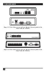
Page 10: ... and 2 2 on the next page These switches control the data rate data bits parity voltage and line or port specifications for configuring the unit to work with the DTE device The telephone line ports are located on the rear panels of the Caller ID units also shown in Figures 2 1 and 2 2 on the next page You ll use regular modular phone cable to attach these RJ 14C TE120A or RJ 11C TE121A input jacks...

Page 11: ...AND 8 LINE CALLER ID Figure 2 1 Front shown at top and rear shown at bottom panels of the 4 Line Caller ID TE120A Figure 2 2 Front shown at top and rear shown at bottom panels of the 8 Line Caller ID TE121A ...

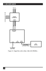
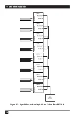
Page 12: ...o the RS 232 OUT port It will light its DATA LED to indicate that it s sending data through its RS 232 OUT port The flow of the data in systems with a single Caller ID unit is shown in Figures 2 3 and 2 4 on the next two pages the data flow in systems with multiple daisychained Caller ID units is shown in Figures 2 5 and 2 6 on the pages that follow What happens to the data after the Caller ID uni...

Page 13: ...12 4 AND 8 LINE CALLER ID Figure 2 3 Signal flow with a 4 Line Caller ID TE120A ...

Page 14: ...13 CHAPTER 2 Introduction Figure 2 4 Signal flow with an 8 Line Caller ID TE121A ...

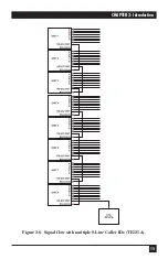
Page 15: ...14 4 AND 8 LINE CALLER ID Figure 2 5 Signal flow with multiple 4 Line Caller IDs TE120A ...

Page 16: ...15 CHAPTER 2 Introduction Figure 2 6 Signal flow with multiple 8 Line Caller IDs TE121A ...

Page 17: ...is means that it actually transmits data on its Receive Data lead as a modem would It s designed to be connected to printers terminals PCs running terminal emulators and other DTEs In daisychained applications it can be connected to the RS 232 IN port of the next Caller ID unit in the chain The RS 232 OUT port is pinned this way Pin Signal Direction 1 Carrier Detect CD Out to other device 2 Receiv...

Page 18: ...ler ID unit 5 Signal Ground SGND N A 7 Request to Send RTS Out to other Caller ID unit 8 Clear to Send CTS In from other Caller ID unit 9 Busy In from other Caller ID unit 2 4 The Complete Package Each 4 Line Caller ID comes with 2 Condenser cables with two RJ 11C plugs at one end and one RJ 14C plug at the other end Power supply This manual Each 8 Line Caller ID comes with 1 Standard phone cable ...

Page 19: ...r damage attached equipment Positions 1 and 2 govern how Pin 1 Carrier Detect CD is handled 1 OFF 2 OFF Pin 1 output is disabled factory default setting 1 ON 2 OFF Causes continuous 12 VDC output on Pin 1 1 OFF 2 ON Causes continuous 12 VDC output on Pin 1 Positions 3 4 and 5 govern how Pin 6 Data Set Ready DSR is handled 3 OFF 4 OFF 5 OFF Pin 6 output is disabled factory default setting 3 ON 4 OF...

Page 20: ...FF 7 data bits 3 ON 8 data bits factory default setting Use positions 4 and 5 to set the parity of the RS 232 OUT port 4 OFF 5 OFF No parity factory default setting 4 ON 5 OFF Odd parity 4 OFF 5 ON or 4 ON 5 ON Even parity Use positions 6 7 and 8 to set the unit number 1 for a single unit or 1 2 etc for daisychained units successively closer to the DTE For example if you have three 4 Line units in...

Page 21: ...ou d place one of the two 4 Line units and number it 6 and you d place the second 4 Line unit at the head of the chain attached to the DTE and number it 7 1 Attach line splitters or cross connects to your site s phone line jacks so that you can send the incoming phone signals to both your telephones and the Caller ID system If it s not possible to plug cross connects directly into your site s phon...

Page 22: ...lines on separate connectors 5 Run an RS 232 cable not included from the DB9 female RS 232 OUT port of your single Caller ID unit or the first highest numbered unit in your daisychain to an RS 232 serial port on the DTE that will be receiving the Caller ID information If the DTE is a PC running terminal emulation and you re connecting the Caller ID unit to one of its DB9 male serial ports you ll n...

Page 23: ...Line units Two 8 Line units four 4 Line units Three 8 Line units two 4 Line units If you use four or more 8 Line units you can t include any 4 Line units 7 Attach the output cord of each Caller ID unit s power supply to the Power connector on the back of the unit 8 Plug each power supply s input cord into a working AC outlet The corresponding Caller ID unit should power up immediately it has no ON...

Page 24: ... company s central office as Bell 202A modem tones between the first and second rings of the phone call The Caller ID unit takes this information formats it as an ASCII text record as shown in Figure 5 1 prefaces it with the number of the port on which the call was received and sends it from its RS 232 OUT port to the DTE NOTE If handshaking between the Caller ID system and the DTE is prolonged da...

Page 25: ... Caller ID unit sometimes fills this field the Time field that follows and the filler between them with right justified text such as MESSAGE WAITING MESSAGE RETRIEVED and INVALID DATA Time 8 characters The time of day in hour minute AM PM format when the call was received Phone Number 14 characters including dashes The first 11 digits of the phone number of the calling party When you are called by...

Page 26: ... plugged into a working AC outlet Try to place a call to one of the lines attached to that Caller ID unit If the system behaves normally otherwise that LED is defective If the call or the Caller ID data is delayed or lost or if the unit doesn t respond at all something else in the unit is defective Call Black Box Tech Support as described in Section 6 3 Caller ID data for some or all lines isn t p...

Page 27: ...o not attempt to alter or repair it It is not user serviceable Contact Black Box Technical Support at 724 746 5500 Before you do make a record of the history of the problem We will be able to provide more efficient and accurate assistance if you have a complete description including the nature and duration of the problem when the problem occurs the components involved in the problem any particular...

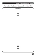
Page 28: ...27 APPENDIX Wallmount Template for 4 Line Unit Appendix Wallmount Template for 4 Line Unit TOP front panel ...

Page 29: ...NOTES ...
Page 30: ...1000 Park Drive Lawrence PA 15055 1018 724 746 5500 Fax 724 746 0746 Copyright 2001 Black Box Corporation All rights reserved ...

Reviews:

Related manuals for TE120A