9
CHAPTER 2: Introduction
2. Introduction
2.1 Overview
The 4- and 8-Line Caller ID units (product codes TE120A and TE121A
respectively) receive Caller ID (identification) data from the telephone company
and send the data, in ASCII RS-232C format, to a printer, terminal, computer, or
other DTE (data terminal equipment). As an interface, the Caller ID unit only
receives, converts, and then resends the the Caller ID information to a DTE device
(not included). Any printing or displaying of the data is done by the DTE.
The Caller ID unit is compatible with most key systems and PBXes, and is also
compatible with most of the current C.O.-based message-waiting services. This
device is single- and multiple-message compatible. Caller ID services are currently
being offered by many telephone companies as a subscribed service (check for
service availability).
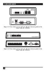
The Caller ID units have one or two 8-position DIP switches on their front panels
(shown in Figures 2-1 and 2-2 on the next page). These switches control the data
rate, data bits, parity, voltage, and line or port specifications for configuring the
unit to work with the DTE device.
The telephone-line ports are located on the rear panels of the Caller ID units
(also shown in Figures 2-1 and 2-2 on the next page). You’ll use regular modular
phone cable to attach these RJ-14C (TE120A) or RJ-11C (TE121A) input jacks to
the incoming telephone lines from the central office. You’ll be using line splitters
or cross-connects to attach the Caller ID units “in parallel” with the telephone
devices associated with those lines (see
Chapter 4
).
The Caller ID unit’s power-supply connector is also located on its rear panel.
The power supply is an external AC-power adapter requiring a common AC outlet.
On the rear panel there are also two connectors, RS-232 IN and RS-232 OUT,
which you can use to daisychain (interconnect) as many as eight Caller ID units in
order to monitor up to 32 or 64 lines or ports with a single RS-232 connection to a
DTE. (32 will be the maximum number of lines if you use any 4-port units; 64 will
be the maximum if you use only 8-port units.)
Summary of Contents for TE120A
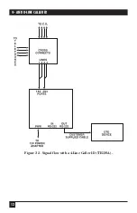
Page 13: ...12 4 AND 8 LINE CALLER ID Figure 2 3 Signal flow with a 4 Line Caller ID TE120A ...
Page 14: ...13 CHAPTER 2 Introduction Figure 2 4 Signal flow with an 8 Line Caller ID TE121A ...
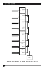
Page 15: ...14 4 AND 8 LINE CALLER ID Figure 2 5 Signal flow with multiple 4 Line Caller IDs TE120A ...
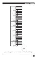
Page 16: ...15 CHAPTER 2 Introduction Figure 2 6 Signal flow with multiple 8 Line Caller IDs TE121A ...
Page 29: ...NOTES ...


