background image

9

CHAPTER 3: Installation and Operation

3. Installation and Operation

3.1 Front Panel

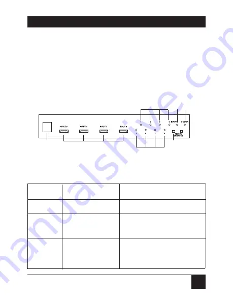
Figure 3-1 shows the 8 to 1 HDMI Switch’s front panel.
Table 3-1 describes its components.

Figure 3-1. Front panel.

Table 3-1. Front panel components.

Component

Name

Description

Remote control sensor

IR receiver

HDMI inputs 5–8

Using HDMI cable, connect your various
HDMI sources to the switch’s HDMI
inputs.

Input select button/

Press the Input button repeatedly to 

indicators

switch to your desired input source. The
corresponding LED lights to indicate
which source (1–8) is being selected.

Summary of Contents for SW216A

Page 1: ...1000 Park Drive Lawrence PA 15055 1018 724 746 5500 Fax 724 746 0746 Copyright 2008 Black Box Corporation All rights reserved...

Page 2: ...e in the U S Call 877 877 BBOX outside U S call 724 746 5500 FREE technical support 24 hours a day 7 days a week Call 724 746 5500 or fax 724 746 0746 Mailing address Black Box Corporation 1000 Park D...

Page 3: ......

Page 4: ...nt is operated in a commercial environment Operation of this equipment in a residential area is likely to cause interference in which case the user at his own expense will be required to take whatever...

Page 5: ...lavabo s tano mojado o cerca de una alberca etc 6 El aparato el ctrico debe ser usado nicamente con carritos o pedestales que sean recomendados por el fabricante 7 El aparato el ctrico debe ser montad...

Page 6: ...contactos y recept culos donde salen del aparato 14 El equipo el ctrico debe ser limpiado nicamente de acuerdo a las recomendaciones del fabricante 15 En caso de existir una antena externa deber ser l...

Page 7: ...RADEMARKS USED IN THIS MANUAL BLACK BOX and the Double Diamond logo are registered trademarks of BB Technologies Inc Any other trademarks mentioned in this manual are acknowledged to be the property o...

Page 8: ...2 Overview 7 2 1 Introducion 7 2 2 What s Included 7 2 3 Features 7 3 Installation and Operation 9 3 1 Front Panel 9 3 2 Rear Panel 10 3 3 Remote Control 12 3 4 Console Control 13 3 4 1 Modem Cable 13...

Page 9: ...Enhance button 1 Input button Connectors Input 8 HDMI Type A female Output 1 HDMI female single link RS 232 1 DB9 Power 1 9 VDC power connector Indicators 10 LEDs 8 Input Source 1 Signal Enhance 1 Pow...

Page 10: ...emote control Simply press a button to select your desired HDMI source for display on the HDTV 2 2 What s Included 8 to 1 HDMI Switch Remote control Power supply This user s manual 2 3 Features HDMI 1...

Page 11: ...H Ideal for home theater integration Supports high resolution input PC VGA SVGA XGA SXGA and UXGA 1600 x 1200 HDTV 480i 576i 480p 576p 720p 1080i and 1080pi Includes remote control Easy to install and...

Page 12: ...1 Front panel Table 3 1 Front panel components Component Name Description Remote control sensor IR receiver HDMI inputs 5 8 Using HDMI cable connect your various HDMI sources to the switch s HDMI inpu...

Page 13: ...ton indicator turn on this feature to improve signal quality after long distance transmission Press again to turn off The LED lights when the signal is enhanced Power LED indicator The LED lights when...

Page 14: ...ing HDMI cable connect the HDMI output to your display s HDMI input HDMI inputs 1 4 Using HDMI cable connect your various HDMI sources to the switch s inputs Power connector Plug the supplied 5 VDC po...

Page 15: ...e 3 3 describes its components Figure 3 3 Remote control Table 3 3 Remote control s components Component Name Description Power Press this button to turn the switch on off Direct input selector Press...

Page 16: ...le 3 4 Table 3 4 Modem cable pinout Splitter Side of the Cable Remote Controller or Console Side of the Cable Pin Definition Pin Definition 1 N C 1 N C 2 TxD 2 RxD 3 RxD 3 TxD 4 N C 4 N C 5 GND 5 GND...

Page 17: ...tcher responds with an either an OK message if the command is legal or an NG message if the command is not legal NOTES The command must be combined with characters and digits The combination command c...

Page 18: ...mands Command Code Comment Port 1 Port 1 ON Port 2 Port 2 ON Port 3 Port 3 ON Port 4 Port 4 ON Port 5 Port 5 ON Port 6 Port 6 ON Port 7 Port 7 ON Port 8 Port 8 ON Signal 1 Enable Signal Enhance Signal...

Page 19: ...16 8 TO 1 HDMI SWITCH 3 5 Typical Application Figure 3 4 Typical application LCD TV DVD 1 DVD 2 DVD 3 Set top box...

Reviews: