background image

Chapter 4: Configuration

724-746-5500   |   blackbox.com 

Page 25

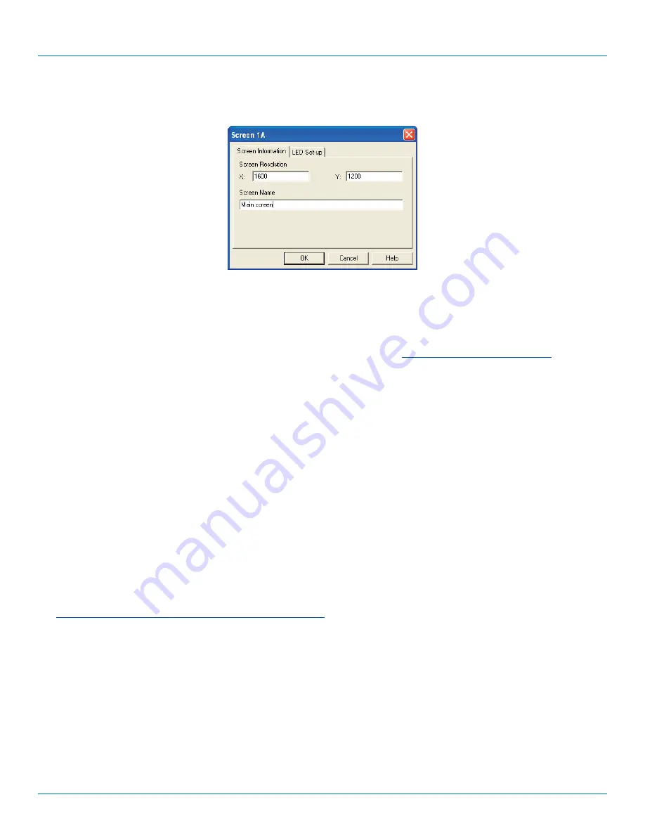
3. Double-click on each screen representation to set the screen resolution and, optionally, add a screen name and/or configure 

an LED indicator (if used). See Figure 4-3.

Figure 4-3. Defining the resolution of a screen and (optionally) a name 

  The screen resolutions are not critical but they enable the ServSwitch Freedom unit to accurately map the movement of the 

mouse onto corresponding movements of the pointer across the screens. The screen names, if used, are not downloaded to 
the ServSwitch Freedom unit. 

  If you need to configure an LED indicator, click the LED Setup tab. Please see 

4.5 Configuring LED indicators

 for details.

4. When the screen map is complete and accurately matches the true layout of the display screens, click 

File

 and choose the 

Save


option to store a copy of the layout. The layout will be stored as a ‘Glide and Switch Config file’ with the extension: 

.ffc

5. Ensure that the upgrade cable is correctly installed - see Section ‘4.3.1 Installing the Glide and Switch configuration application’.

  Click the 

Configure

 menu and choose the 

Connection...

 option to ensure that the correct computer serial port is selected 

and that the Baud Rate matches that of the ServSwitch Freedom unit (1200 is the default speed). 

6. To send the configuration, click the 

Send Layout to Switch

 option. 

•  If the download is successful, the screen representations will briefly turn gray and the upper four indicators on the 

ServSwitch Freedom unit will begin to scroll across (they will continue to do this while Glide and Switch mode is enabled).

•  If the download is unsuccessful, a message dialog will explain that it is ‘Unable to communicate with the device’. Check the 

upgrade cable, check that the correct serial port is selected and check that the connection speed shown within the utility 
matches the speed used on the ServSwitch Freedom unit.

7. 

IMPORTANT: Once the Glide and Switch configuration application has downloaded the setup, remove and recon-
nect power to the ServSwitch Freedom switch.


See 

4.6 Optional Glide and Switch operations and settings

Summary of Contents for ServSwitch KV0004A

Page 1: ...24 746 5500 or fax 724 746 0746 Mailing address Black Box Corporation 1000 Park Drive Lawrence PA 15055 1018 Web site www blackbox com E mail info blackbox com Customer Support Information NETWORK SER...

Page 2: ...is a registered trademark of Novell Inc Sun is a trademark of Sun Microsystems Inc Unix is a registered trademark of UNIX System Laboratories Inc BSD is a registered trademark of UUNet Technologies I...

Page 3: ...en the equipment is operated in a commercial environment Operation of this equipment in a residential area is likely to cause interference in which case the user at his own expense will be required to...

Page 4: ...dan el flujo de aire por los orificios de ventilaci n 10 El equipo el ctrico deber ser situado fuera del alcance de fuentes de calor como radiadores registros de calor estufas u otros aparatos incluye...

Page 5: ...21 4 2 2 Mouse switching 21 4 2 3 OPTIONS port speed 21 4 2 4 Switching mode 22 4 2 5 Miscellaneous functions 23 4 3 Glide and Switch configuration 24 4 4 Multi Monitor Glide and Switch configuration...

Page 6: ...Unix BSD all Sun OS all Mac OS NetWare etc Connectors Keyboard Mouse USB Type A female Switched USB USB 2 0 Type A female Audio 3 5 mm stereo jack Other Modular 10p10c for Flash upgrade and channel s...

Page 7: ...nected to the ServSwitch Freedom can be achieved in five different ways The innovative Glide and Switch automatic switching utility see Appendix B The COMPUTER button on the top panel Keyboard hotkey...

Page 8: ...on critical computer systems True Emulation Earlier USB KVM switches relied upon standard keyboard and mouse templates to tell each computer system how to deal with the connected peripherals The ServS...

Page 9: ...Indicators The lower four indicators K M SPK USB1 USB2 show which peripherals are switched to the current computer channel or as you begin pressing the MODE button the peripherals that will be switche...

Page 10: ...s used to allow external control of channel switching and also to update the internal firmware when necessary by connecting to a computer 8 4 USB Type B connectors Connect to a USB port on each comput...

Page 11: ...ons listed within the Safety information section 3 2 Mounting Before you begin connecting to the keyboard mouse and source systems it is advisable to mount the ServSwitch Freedom unit in place either...

Page 12: ...peripheral devices in the vicinity of the unit so that their cables will easily reach 2 Keyboard and mouse Attach the leads from your USB keyboard and mouse to the USB sockets specifically labeled wit...

Page 13: ...mputer system 1 Ensure that power is disconnected from the ServSwitch Freedom unit and the system to be connected 2 Use a USB cable type A to type B to link a USB port on the computer system to the US...

Page 14: ...ead to the power input socket 2 Connect the IEC connector of the supplied country specific power lead to the socket of the power adapter See Figure 3 6 Figure 3 6 Attaching the IEC connector of the po...

Page 15: ...nsmit TXD line of the computer to the receive RXD input of the unit and also link the ground terminals GND of the two devices See Appendix C for details 1 Insert the 8p8c or 10p10c connector of the ca...

Page 16: ...he following Baud rate 1200 Data bits 8 Stop bit 1 Parity None Serial port channel selection codes ASCII Character Hex Decimal Channel 1 1 0x31 49 Channel 2 2 0x32 50 Channel 3 3 0x33 51 Channel 4 4 0...

Page 17: ...o if the module is temporarily disconnected from the switch during operation communication between the two will cease and the switch will need to be re powered with the ServSwitch Freedom LED Monitor...

Page 18: ...r with 3 metre lead Port 2 Port 3 Port 4 Insert the lead for the first indicator into port 1 Each indicator has a self adhesive Velcro tab to assist with mounting on your video displays Flash upgrade...

Page 19: ...five seconds The display will show C 2 On the keyboard press the letter key for the required menu section e g S see Table 4 1 for full list of options The display will show the pressed letter 3 Press...

Page 20: ...played momentarily H Enter the Hotkey menu 1 Ctrl Alt default 2 Ctrl Shift 3 Alt Shift 4 Right Alt 5 Alt 6 Left Ctrl Alt 7 Right Ctrl Alt 8 Hotkeys disabled P Set a new password for use with the lock...

Page 21: ...To enable disable mouse switching 1 Enter the Configuration menu see Section 4 1 for details 2 Press U to enter the User Preferences menu and then press either 1 to Enable mouse switching 2 to Disable...

Page 22: ...switching methods the RS 232 serial signal input will switch the peripherals as defined by the currently selected switching mode However switching control initiated by the channel select input lines w...

Page 23: ...s menu 3 Press 1 and then Enter The display will blank for a short while and then the major number of the firmware revision will be shown The display will blank again and then show the first digit of...

Page 24: ...nitor module see 3 3 5 Optional LED monitor indicator connections for details 3 Start the configuration application 4 3 2 Configuring the Glide and Switch system Use the Glide and Switch configuration...

Page 25: ...the upgrade cable is correctly installed see Section 4 3 1 Installing the Glide and Switch configuration application Click the Configure menu and choose the Connection option to ensure that the correc...

Page 26: ...ication and needs to be installed only on the PC that will be used to set up the ServSwitch Freedom switch via the supplied flash upgrade cable and OPTIONS port Visual C Runtime The C runtime library...

Page 27: ...display screens per computer to the map area For example to add two monitors for PC 1 click the red computer icon twice The two red monitor representations will be placed side by side within the Glid...

Page 28: ...fault color on all connected indicators choose the required Default color and then tick the option Set all LEDs to this color Use the Default brightness option to determine the intensity of all indica...

Page 29: ...es to one of the ten output sockets on the ServSwitch Freedom LED Monitor module Note It is possible to associate any LED indicator with more than one video screen Figure 4 8 Choosing a color for the...

Page 30: ...to a different system video screen The Configure Mouse parking option displays vertical and horizontal scroll bars Use the scroll bars to pinpoint the position that should be used to park the dormant...

Page 31: ...d copy all contained files to the same folder on the upgrade computer 2 Remove the power supply plug from the rear panel of the unit 3 Use the supplied Flash Upgrade Adapter and any CAT5 patch cable t...

Page 32: ...d at any stage click the Abort button response to this is usually immediate however during an erase command the upload will not be aborted until the erase is complete this may take a few seconds 9 Dis...

Page 33: ...ch configuration The mouse will not flow across the screens while any mouse buttons are pressed down this prevents undesired behavior when dragging windows around or group selecting items You can dete...

Page 34: ...pressing the MODE button the peripherals that will be switched during the next press es of the COMPUTER button Use this button to choose the next required computer Indicates the number of the currentl...

Page 35: ...itched using this method depend upon the switching mode that is currently set using the front panel buttons The range of standard hotkey combinations are as follows Note If your hotkeys have been chan...

Page 36: ...Note These procedures work only with three button or IntelliMouse devices and only if the Mouse Switching option has been enabled To select a computer using the mouse buttons 1 Hold down the middle b...

Page 37: ...Enter The password is not case sensitive and can be any combination of key strokes including the function keys but excluding the Num Lock Caps Lock Scroll Lock and Enter keys If your keyboard has spe...

Page 38: ...creation of the Emulated USB switch A neat side effect of the technique used is that each computer can be fooled into thinking that the USB device is permanently connected to it even when the device i...

Page 39: ...s that are jointly used with the True Emulation system Because they interface directly and permanently with each computer they help to stabilize the dormant links making errors during enumeration much...

Page 40: ...rmation etc You then download this information to the ServSwitch Freedom unit and this is used during operation to determine the precise moment to switch from one screen system to the next The beauty...

Page 41: ...trol and flash upgrade cable 10p10c 10p10c connector D Type female 9 way 7 2 TXD RXD 4 3 3 5 RXD GND TXD GND Appendix C Cable pin outs The OPTIONS port uses a 10p10c socket which can accommodate both...

Page 42: ...ained within power adapter No user serviceable parts within power adapter do not dismantle Plug the power adapter into a socket outlet close to the module that it is powering Replace the power adapter...

Page 43: ...ted by free live 24 7 Tech support available in 20 seconds or less Copyright 2013 All rights reserved Black Box and the Double Diamond logo are registered trademarks of BB Technologies Inc Any third p...

Reviews: