11
CHAPTER 5: Operation
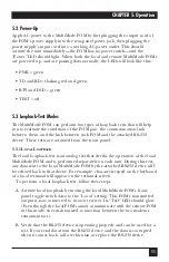
5.2 Power-Up
Apply AC power to the MultiMode FOM by first plugging the output cord of
the FOM’s power supply into the rear-panel power jack, then plugging the
power supply’s input cord into a working AC power outlet. This should
activate the unit immediately—the FOM has no power switch—and the
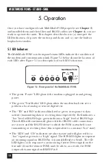
“Power” LED should light. When both the local and remote MultiMode FOMs
are powered up, and are passing data normally, the LEDs will look like this:
• PWR = green
• TD and RD = flashing red and green
• RTS and DCD = green
• TEST = off
5.3 Loopback-Test Modes
The MultiMode FOM can perform two types of loopback tests that will help
you to evaluate the condition of the FOM pair, the communication link
between them, and the link between each FOM and the attached RS-232
device. These tests are activated from the front panel.
5.3.1 L
OCAL
L
OOPBACK
The local loopback test is an analog test that checks the operation of the local
MultiMode FOM, and is performed separately on each unit. During this test,
any data sent to the local MultiMode FOM by the attached RS-232 device will
be echoed back to that device. For example, characters typed on the keyboard
of a local terminal will appear on the terminal screen.
To perform a local loopback test, follow these steps:
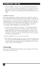
A. Activate local loopback by moving the local MultiMode FOM’s front-
panel toggle switch
down
to the “Local” setting: This FOM’s transmitted
output is now connected to its own receiver. Its “Test” LED should glow.
(Even though the local FOM cannot communicate with the remote FOM
in this mode, the synchronized connection between the two modems
remains intact.)
B. Verify that the RS-232 device is operating properly and can be used for a
test. If you send data from the RS-232 device and the data is corrupted
when it comes back, call a technician or replace the RS-232 device.


