background image

724-746-5500   |   blackbox.com 

Page 36

724-746-5500   |   blackbox.com 

802.3af and 802.3at PoE Gigabit Injectors

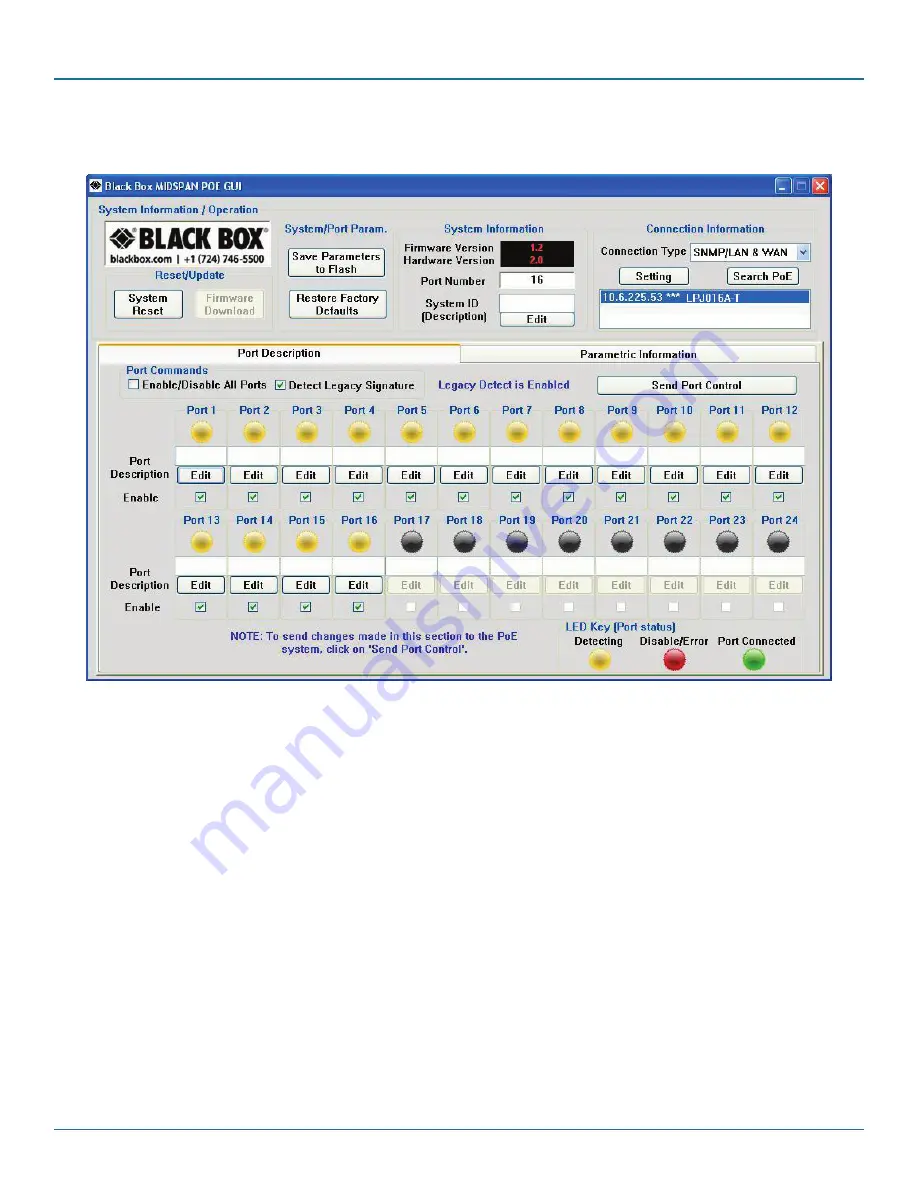
 NOTE: The IP address will be saved internally for the next use.

Figure A-18. GUI main window.

All features except for the Firmware Download are supported. Please refer to Chapter 5 for the full description of the Black Box 
GUI features. To update firmware using SNMP, refer to Section A.3.

Summary of Contents for LPJ008A-F

Page 1: ...16A F LPJ024A F LPJ008A FM LPJ016A FM LPJ024A FM LPJ008A T LPJ016A T LPJ008A TM LPJ016A TM Order toll free in the U S Call 877 877 BBOX outside U S call 724 746 5500 FREE technical support 24 hours a day 7 days a week Call 724 746 5500 or fax 724 746 0746 Mailing address Black Box Corporation 1000 Park Drive Lawrence PA 15055 1018 Web site www blackbox com E mail info blackbox com Customer Support...

Page 2: ...or go to blackbox com and click on Talk to Black Box You ll be live with one of our technical experts in less than 30 seconds Trademarks Used in this Manual Black Box and the Double Diamond logo are registered trademarks of BB Technologies Inc Windows is a registered trademark of Microsoft Corporation Any other trademarks mentioned in this manual are acknowledged to be the property of the trademar...

Page 3: ...en the equipment is operated in a commercial environment Operation of this equipment in a residential area is likely to cause interference in which case the user at his own expense will be required to take whatever measures may be necessary to correct the interference Changes or modifications not expressly approved by the party responsible for compliance could void the user s authority to operate ...

Page 4: ...etes que impidan el flujo de aire por los orificios de ventilación 10 El equipo eléctrico deber ser situado fuera del alcance de fuentes de calor como radiadores registros de calor estufas u otros aparatos incluyendo amplificadores que producen calor 11 El aparato eléctrico deberá ser connectado a una fuente de poder sólo del tipo descrito en el instructivo de operación o como se indique en el apa...

Page 5: ...stallation 14 4 Black Box GUI and USB Driver Installation 15 4 1 PC to PoE Gigabit Injector GUI 15 4 2 PC to PoE Gigabit Injector Connection via USB RS 232 15 4 3 Device Manager to View Port Properties 16 4 4 USB Block Diagram 18 5 GUI Operation 19 5 1 GUI Main Window 19 5 2 GUI System Information Operation 20 5 3 GUI Port Description 21 5 4 GUI Parametric Information 22 6 Troubleshooting 23 Appen...

Page 6: ...LPJ008A TM LPJ016A FM LPJ016A TM LPJ024A FM Also Ethernet SNMP port 1 RJ 45 Indicators LPJ008A F LPJ008A FM LPJ016A F LPJ016A FM LPJ024A F LPJ024A FM Green LED Power detected ON LPJ008A T LPJ008A TM LPJ016A T LPJ016A TM Green LED Power detected CONNECT LPJ008A T LPJ016A T LPJ016A TM Flashing green LED 802 3af detected CONNECT at 15 4 W All models Yellow LED Fault detected Power AC input voltage ra...

Page 7: ...rity system cameras wireless network access points Bluetooth access points and other 802 3af at compatible equipment Enables you to avoid the cost and hassle of installing AC power at remote cameras or door scanners Supports 10 100 1000 Mbps PoE Gigabit Injector data connections on 8 16 or 24 RJ 45 inputs outputs Protection includes overvoltage overcurrent overload and short circuit protection on ...

Page 8: ...t panel of the 24 port PoE Gigabit Injector Figures 2 2 and 2 3 show close up views of front panel components Table 2 1 describes the front panel components 1 2 4 5 3 Figure 2 1 Front panel 24 port units 1 2 Figure 2 2 Close up of front panel data power and data ports 4 3 5 Figure 2 3 Close up of front panel Ethernet and USB Type B connectors ...

Page 9: ... Links to network interface card only LPJ008A FM LPJ016A FM LPJ024A FM LPJ008A TM LPJ016A TM models have this connector 4 USB Type B connector Links to USB 5 AC LED Lights when AC power is connected 2 4 2 Back Panel Figure 2 4 shows the back panel of the 24 port PoE Gigabit Injector Figure 2 5 shows a close up view of the AC power connector 6 Figure 2 4 Back panel Figure 2 5 IEC 320 3 pin AC power...

Page 10: ...ound in the PoE Injector User Manual To download a copy of the manual visit ftp blackbox com 3 To prevent the PoE Injector from overheating do not operate the product in an area that exceeds the maximum recommended ambient temperature of 40 C Allow at least 3 to 4 inches of clearance around all ventilation openings 4 To support the PoE Injector weight do not stack the chassis on any other equipmen...

Page 11: ...must comply with section 108 2 D1 standard DK2 1a or DK2 5a United Kingdom The PoE Gigabit Injector is covered by General Approval section 16 16 060 NS G 12345 J100003 for indirect connection to a public telecommunication system France and Peru IT equipment cannot power this device In the case of an IT powered device the unit needs to be powered by 230V through an isolation transformer with a rati...

Page 12: ...r with Ethernet cables connected to data and power ports Figure 3 2 Close up view of PoE GIgabit Injector with cable connected to Ethernet port 3 3 Connecting USB and Power Cables USB cable Connect a USB cable not included to the USB Type B connector located on the front side of the PoE Gigabit Injector and a USB port on your PC laptop See Figures 3 3 and 3 4 USB Type B connector connects to the U...

Page 13: ...hich takes less than 10 seconds During this period all ports are initially disabled and the port indicators light up The sequence of the port LEDs are shown in Section 3 5 Ports are now operating under normal conditions 3 5 LED Indicators 3 5 1 Cold Start 1 AC LED turns greenÆremains on 2 Ethernet LED turns greenÆredÆgreenÆturns offÆredÆturns off unless connected 3 24 ports with ports connected ÆL...

Page 14: ...disconnected but enabled Ethernet LED Indicates Ethernet is N A Indicates NIC is N A disconnected from connected to network network AC LED Indicates PoE Gigabit Indicates PoE Gigabit N A N A Injector is not powered Injector is powered 3 6 Rackmounting Installation Position the PoE Gigabit Injector on the rack Line up the mounting bracket with the corresponding screw holes on the PoE Gigabit Inject...

Page 15: ... driver to communicate with the PoE Gigabit Injector via a Communication Port on the PC See Figures 4 1 and 4 2 Figure 4 1 Example of the GUI setup window NOTE Call Black Box Technical Support 724 746 5500 to make sure you are installing the latest version of the Black Box GUI The example shown uses POE SNMPv3 GUI 4 2 PC to PoE Gigabit Injector Connection via USB RS 232 Using a USB RS 232 cable co...

Page 16: ...above your PC will locate the new hardware To view which Serial COM Port your PoE Gigabit Injector is installed on follow these instructions 1 Click Start Control Panel System System Properties See Figure 4 3 Figure 4 3 System Properties screen Click and the following window will open Figure 4 4 Device Manager screen Locate and expand ports COM and LPT Double click the Prolific USB to Serial Comm ...

Page 17: ...e sure the Port Setting is as shown Click Click on the pull down menu and select the Com Port Number or stay with the default Figure 4 6 Prolific USB to Serial Comm Port Properties Advanced Settings screen Click to save all changes NOTE Write down the COM Port number because the GUI will need to know the exact port on which to search for devices ...

Page 18: ...to respond USB port PC The PC automatically detects the newly installed hardware This function is called plug and play and is available with a USB connection The PC quickly identifies the connection as serial COM Windows will automatically install your device on an available serial COM port You can make changes via Device Manager Figure 4 7 USB block diagram NOTE If the USB to Serial Comm Port dri...

Page 19: ... Injector system If you have successfully installed the Black Box GUI and USB driver as described in Chapter 4 go to the GUI on your desk top or from your Start Menu 5 1 GUI Main Window Step 1 Choose the connection type See FIgure 5 1 Figure 5 1 GUI main window Step 2 Select the COM port number click Search PoE and highlight the PoE Gigabit Injector Figure 5 2 GUI connection information ...

Page 20: ...and is selected more than once within two seconds the GUI may not respond properly The Save Parameters to Flash button will save system and port parameters to flash memory so that they can be used to retain the firmware across reboots of the unit The Restore Factory Defaults button will reset the defaults in the firmware and clear any stored data in the flash memory so the device will reset automa...

Page 21: ... permanent you must click Save Parameters to Flash Enable This check box can administratively enable or disable the selected port If you select the Enable Disable All Ports check box all ports will be enabled Initially the checkbox is not checked by default all ports are enabled Click Send Port Control to send the command to the system To make this permanent you must click Save Parameters to Flash...

Page 22: ...istance of the port in ohms Current mA This value represents the current I of the port in milliamps Voltage V This value represents the voltage V of the port Power mW This value represents the power of the port in milliwatts Class Current mA This value represents the class current of the port in milliamps Determined Class This value represents the class of the discovered device NOTE In Figure 5 7 ...

Page 23: ...ve Port LEDs to verify proper power up Problem AC LED is not lit Possible Solution Verify that the PoE Gigabit Injector is properly connected to an AC power source Problem Port LEDs do not light green Possible Solution 1 Port may be disabled and needs to be enabled using the GUI Make sure the ports are enabled then Save Flash Parameters Possible Solution 2 Make sure the ports are connected to a ne...

Page 24: ...P MIB text file to the file extension that matches your SNMP console Follow the instructions for your SNMP console to install the MIB file Please check ftp blackbox com occasionally for the latest updates for the MIB and SNMP firmware Example of a SNMP Firmware file please check our Web site for updates 2 Visit ftp blackbox com to download the Ethernet Manager tool etm exe Etm exe is a Device Mana...

Page 25: ...ox com Page 25 Appendix A Optional Ethernet Interface Figure A 2 Ethernet manager screen 5 If your device is not found check the connection and click View Refresh See Figure A 3 Figure A 3 Refresh Ethernet manager screen ...

Page 26: ...IP address in your Internet browser Your Internet browser will open with the following window Figure A 4 Controller login screen 1 Click Setup Login 2 Default User admin lower case 3 Default Password leave area blank NOTE If you forget your login password contact Black Box Technical Support at 724 746 5500 For up to date contact information visit our Web site www blackbox com ...

Page 27: ...in window Port Status The main window of the controller is a simple GUI that allows the user to enable and disable PoE Gigabit Injector ports It is also a limited display of parametric information A more complete list of parametric information is available using the Black Box GUI soft ware available at ftp blackbox com ...

Page 28: ...ord make sure to write it down in a safe place for reference Click to make any changes permanent OK Settings have been saved successfully Click to reboot the system with the new changes This may take a few minutes depending on the connection speed Check the PoE Gigabit Injector IP Address again as it may have changed depending on the user settings for DHCP client Click to review or make additional...

Page 29: ...DHCP mode disabled Gateway Address 192 168 0 1 Four groups of numbers assigned by the network server DHCP mode enabled or user defined DHCP mode disabled DNS Server 168 95 192 1 Four groups of numbers assigned to the network server DHCP Client Enable The default setting Enable sets the DHCP client in Dynamic mode Dynamic mode allows the network server to automatically assign the IP address sub net...

Page 30: ...ck Browse then locate your firmware file it will have a bin file extension Then click Update Firmware file example ROM bin 4 096 KB BIN File 7 29 2009 10 42 AM Restore Default Settings This function is used to revert back to the default settings for the firmware This will undo any changes that you ve so far made to the firmware configuration After using this function users will have the option to ...

Page 31: ...te Set option to public or private User Admin Logon name that may be defined by the user If you change it write it down in a safe place for future reference Authentication Mode HMAC MD5 Set encryption to HMAC MD5 or HMAC SHA1 Authentication Password blank User defined password may be left blank or 1 18 characters in length If you change it write it down in a safe place for future reference This op...

Page 32: ...they must remember these to use the Black Box GUI Open the Black Box GUI and locate and click the Setting button See Figure A 10 Figure A 10 GUI connection information A pop up for the User Security Parameters will allow you to enter the correct IP Address of your PoE Gigabit Injector If the user is using the Authentication and Privacy Passwords ensure that SNMPv3 is checked and enter in the corre...

Page 33: ...al Area Connection Status Click on Double click Internet Protocol TCP IP to view the properties If the DHCP Client is set to Disable it is in Static mode You can manually set the IP address subnet mask and gateway address for your PC If the DHCP client is set to Enable it is in Dynamic mode obtain an IP address automatically The network will automatically set the IP address subnet mask and gateway...

Page 34: ...ol Properties screen A 5 Setup NIC PoE Gigabit Injector with Black Box GUI Locate the Black Box PoE GUI on your desktop or from your Start menu Step 1 Choose Connection Type SNMP LAN WAN and click to access User Security Parameters Users should be sure to input the exact device IP address Figure A 15 GUI User Security Parameters screens ...

Page 35: ...oller system setup or the GUI will not detect the PoE Gigabit Injector To verify the IP address for your PoE Gigabit Injector use the Ethernet Manager tool mentioned in earlier sections Figure A 16 GUI User Security Parameters Ethernet Manager screen Step 2 Select Search PoE If a Black Box PoE device is found click to select the device Figure A 17 GUI Connection Information screen ...

Page 36: ...TE The IP address will be saved internally for the next use Figure A 18 GUI main window All features except for the Firmware Download are supported Please refer to Chapter 5 for the full description of the Black Box GUI features To update firmware using SNMP refer to Section A 3 ...

Page 37: ... for all ports Setting this object at a value disable 1 disables detection mechanism for all ports 2 3 6 1 24852 2 2 6 0 poeSystemHWVersion DisplayString Read only System hardware version for the main board 2 3 6 1 24852 2 2 7 0 poeSystemNumberOfChannel INTEGER Read only Number of ports available in the system 2 3 6 1 24852 2 2 8 0 poeSystemProductPartNumber INTEGER Read only LRJ008A 8 LRJ016A 16 ...

Page 38: ...ism for this port Setting this object at a value disable 1 disables the detecton mechanism for this port 2 3 6 1 24852 2 3 1 3 1 24 poePortControlMaxPower INTEGER Read write This command specifies the maximum power in watts to the port 2 3 6 1 4 1 24852 2 3 1 4 0 poePortCurrentStatus INTEGER undercurrent 1 Describes a current port overCurrent 2 status related to the both 3 power generation The ok ...

Page 39: ...etectionStatus INTEGER Read only Off 0 DiscR 1 DiscC 3 RampUp 4 RampDown 5 SampleI 8 SampleV 9 2 3 6 1 4 1 24852 2 3 1 8 1 24 poePortPowerClassifications INTEGER Read only Class0 1 Class1 2 Class2 3 Class3 4 Class4 5 2 3 6 1 4 1 24852 2 3 1 9 1 24 poePortPowerDetectionControl INTEGER Read write Controls the port power detection control 2 3 6 1 4 1 24852 2 3 1 10 1 24 poePortPowerPriority INTEGER C...

Page 40: ...loadTrap NOTIFICATION Overload trap 2 3 6 1 4 1 24852 2 5 4 poePortDiscoveryFailTrap NOTIFICATION Discovery failure trap 2 3 6 1 4 1 24852 2 5 6 poePortDisconnectTrap NOTIFICATION Port disconnect trap 2 3 6 1 4 1 24852 2 5 7 poePortVoltageFailTrap NOTIFICATION Port voltage fail trap The Ethernet interface that the PoE Gigabit Injector performs under is TCP IP UDP port of 161 UDP port 161 for SNMP ...

Page 41: ...E Gigabit Injector The Ethernet PoE Gigabit Injector remains connected on the network domain of 192 168 1 xxx Since Building 1 has a main network server that links all three floors together the computers on the second 192 168 2 xxx and third 192 168 3 xxx floors can also communicate with the Ethernet PoE Gigabit Injector Connection between different network domains Refer to the diagram above Build...

Page 42: ...it Injectors The currently shared pin is an option that could be used to have the power supply inside the PoE Gigabit Injector currently shared with the rectifiers There are no protocols or procedures associated with it other than it s designed only to work with our rectifier system and even then it s not perfect sharing because of the inrush limiting components inside the PoE Gigabit Injector loc...

Page 43: ...cabinets and racks and power and surge protection products to media converters and Ethernet switches all supported by free live 24 7 Tech support available in 30 seconds or less Copyright 2011 All rights reserved Black Box Tech Support FREE Live 24 7 Tech support the way it should be Great tech support is just 30 seconds away at 724 746 5500 or blackbox com LPJ008A T version 2 ...

Reviews: