background image

724-746-5500   |   blackbox.com 

Page 30

Chapter 4: Configuring the Hardened Serial Server

Figure 4-11. TCP server settings.

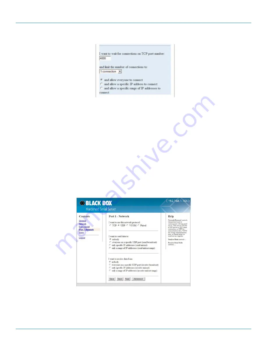
4.7.2 UDP Configuration

UDP (User Datagram Protocol) enables applications using UDP socket programs to communicate with the serial ports on the Hardened 

Serial Server. UDP protocol provides connectionless communications, which allows data to be broadcast to and received from multiple 

nodes on a network.
In UDP mode, if you want to control which network node receives data, you must specify the IP address and UDP port the data will be 

sent to. You can choose to send to: 

• Nobody (Port only in receive mode) 
• All nodes at a specific UDP port number. (This is a broadcast message.) 
• Specific IP addresses and UDP port numbers. (This is a unicast message.) 
• A range of IP addresses and UDP port numbers. (This is a unicast range.) 

You can also configure the Hardened Serial Server to receive from nodes on the network using a similar list of configuration options. 

Figure 4-12. UDP configuration.

Summary of Contents for LES421A

Page 1: ... in 30 seconds or less Copyright 2013 Black Box Corporation All rights reserved Black Box and the Double Diamond logo are registered trademarks of BB Technologies Inc Any third party trademarks appearing in this manual are acknowledged to be the property of their respective owners Black Box Tech Support FREE Live 24 7 Tech support the way it should be Great tech support is just 30 seconds away at ...

Page 2: ... paired mode connections 1 2 and 4 Port Hardened Serial Servers LES421A LES422A LES424A Order toll free in the U S Call 877 877 BBOX outside U S call 724 746 5500 FREE technical support 24 hours a day 7 days a week Call 724 746 5500 or fax 724 746 0746 Mailing address Black Box Corporation 1000 Park Drive Lawrence PA 15055 1018 Web site www blackbox com E mail info blackbox com Customer Support In...

Page 3: ...ur technical experts in less than 30 seconds Trademarks Used in this Manual Black Box and the Double Diamond logo are registered trademarks of BB Technologies Inc Firefox is a registered trademark of Mozilla Foundation Internet Explorer Windows and Windows Vista are registered trademarks of Microsoft Corporation UL Is a registered trademark of Underwriters Laboratories Any other trademarks mention...

Page 4: ...se will be required to take whatever measures may be necessary to correct the interference Changes or modifications not expressly approved by the party responsible for compliance could void the user s authority to operate the equipment This digital apparatus does not exceed the Class A limits for radio noise emis sion from digital apparatus set out in the Radio Interference Regulation of Industry ...

Page 5: ...an el flujo de aire por los orificios de ventilación 10 El equipo eléctrico deber ser situado fuera del alcance de fuentes de calor como radiadores registros de calor estufas u otros aparatos incluyendo amplificadores que producen calor 11 El aparato eléctrico deberá ser connectado a una fuente de poder sólo del tipo descrito en el instructivo de operación o como se indique en el aparato 12 Precau...

Page 6: ...using Hardened Serial Server Software 19 3 5 2 Configuring via the Network using a Browser 19 3 5 3 Configuring via a Serial Port Using Hardened Serial Server Software Console Mode 20 3 6 Hardened Serial Server Operational Connections 20 3 7 Installing and Starting Hardened Serial Server Software 21 3 8 Discovering Hardened Serial Servers 22 4 Configuring the Hardened Serial Server 23 4 1 Overview...

Page 7: ...rmware Files 40 5 2 Uploading the Firmware to the Hardened Serial Server 41 6 Operation 42 6 1 LED Indicators 42 6 2 Reset Switch 45 6 2 1 Using the Reset Switch to Initiate a Hardware Reset 45 6 2 2 Using the Reset Switch to Enter Console Mode 45 6 2 3 Using the Reset Switch to Exit Console Mode 45 6 2 4 Using the Reset Switch to Reload Factory Default Settings 45 7 Diagnostics 46 7 1 Testing a H...

Page 8: ...imum Ambient Surrounding Air Temperature 176 F 80 C Operating Humidity 10 to 95 noncondensing Power LES421A LES422A 10 to 48 VDC 58 VDC max 4 0 watts max LES424A Locking barrel connector input Voltage requirements 10 to 30 VDC maximum Class 2 grounded type supply only NOTE Coaxial power cable must be in accordance with Class 2 requirements in Article 725 of the NEC The locking barrel connector mus...

Page 9: ...ade Via serial Ethernet or auto web search IP Port Addresses 5300 heartbeat and configuration setting in TCP mode i e Pair mode 8888 LES424A update Network Communications LAN 10 100 Mbps auto detecting 10BASE T and 100BASE TX Network Physical Layer Standards Ethernet IEEE 802 3 autodetecting and auto MDI MDI X 10BASE T and 100BASE TX Protocols Supported TCP IPv4 UDP ARP HTTP 1 0 ICMP PING DHCP BOO...

Page 10: ...l port 4 uses 60003 tcp If a port is not configured for paired mode server then the corresponding port is not open If you want to connect to a paired mode server from outside of a firewall then you must allow incoming connections on these ports If you want to connect to a paired mode server from outside of a NAT then you must forward to these ports 60001 tcp This port is open when serial port 2 is...

Page 11: ...724 746 5500 blackbox com Page 10 Chapter 1 Specifications 1 5 Dimensional Diagrams Figure 1 1 Dimensional diagram of a LES421A or LES422A Hardened Serial Server dimensions in inches ...

Page 12: ...724 746 5500 blackbox com Page 11 Chapter 1 Specifications Figure 1 2 Dimensional diagram of a LES424A Hardened Serial Server dimensions in inches and millimeters ...

Page 13: ... time RJ 45 RJ 45 1 2 wire terminal block LES422A 2 2 DB9M RJ 45 RJ 45 1 2 wire terminal block LES424A 4 4 DB9M RJ 45 RJ 45 RJ 45 1 3 wire terminal block and 1 locking barrel connector for redundant power 2 2 Features LES421A LES422A single Ethernet connector LES424A 2 Ethernet connectors Ethernet passthrough ports Multi interface serial ports RS 232 RS 422 RS 485 LES421A has DB9M and pluggable te...

Page 14: ...uide This user manual in PDF format on CD ROM 1 3 position terminal block Phoenix connector 1 Panel mount kit 2 brackets 4 screws 1 DIN rail mounting kit 1 DIN rail bracket 3 screws NOTE To download this user manual go to ftp ftp blackbox com anonymous manuals L LES421A_2A_4A_USER_rev1 pdf or visit the Black Box Web site www blackbox com and enter LES421A LES422A or LES424A in the search bar 2 4 H...

Page 15: ...d connections 5 1 Serial Port LED Flashes green when data is being transmitted or received on the serial port Lights steady green when the serial port is open 6 1 Ethernet Link LED Lights when a connection is made Flashes when there is data traffic on the Ethernet link 7 1 Ready LED Lights green continuously when the unit is initializing Flashes once per second when the system is operating correct...

Page 16: ...eived on the serial port Lights steady green when the serial port is open 5 1 Ethernet Link LED Lights when a connection is made Flashes when there is data traffic on the Ethernet link 6 1 Ready LED Lights green continuously when the unit is initializing Flashes once per second when the system is operating correctly Off when something is wrong for example another device uses the same IP address 7 ...

Page 17: ...et link 5 4 Serial Port LEDs Flashes green when data is being transmitted or received on the serial port Lights steady green when the serial port is open 6 4 DB9 male connectors Connects to RS 232 RS 422 or RS 485 serial devices 7 2 RJ 45 connectors Enable the server to act as an Ethernet switch 8 1 3 wire terminal block connector Removable 3 position terminal block with and chassis ground connect...

Page 18: ...Servers can be connected to serial devices using RS 232 RS 422 RS 485 2 wire or RS 485 4 wire communication LES422A and LES424A models use 2 or 4 DB9 M connectors LES421A models use either 1 DB9 M connector or 1 5 position terminal strip 3 2 1 RS 232 The 2 and 4 port models along with the 1 port model when using its DB9M connector support seven RS 232 signal lines TD RD DTR DSR RTS CTS DCD plus Si...

Page 19: ...half duplex operation The data lines are differential with the Data B line positive relative to Data A in the idle mark state Signal Ground provides a common mode reference for the signal lines NOTE Refer to Appendix B for connector pinout information Serial device Serial connection Network Figure 3 2 LES424A connections 3 3 Connecting RS 232 422 485 Hardened Serial Servers to a Network Ethernet C...

Page 20: ...al Server has been detected you can use the Hardened Serial Server Software to change its settings NOTE For more information on how to use Hardened Serial Server Software to configure your Hardened Serial Server refer to Chapter 4 Configuring the Hardened Serial Server Network Figure 3 4 Network setup 3 5 2 Configuring via the Network using a Browser Hardened Serial Servers can also be configured ...

Page 21: ...itch to enter Console Mode 3 6 Hardened Serial Server Operational Connections Hardened Serial Servers can operate in Direct IP Virtual COM Port and Paired Modes In Direct IP Mode applications can use TCP IP socket connections or UDP IP datagrams to communicate with the COM ports on the serial server In this type of application the serial server is configured as a TCP or UDP server The socket progr...

Page 22: ...and handshake information directly as if they were physically connected in a point to point serial connection Paired Mode devices are set up as shown in the following diagram and configured using Hardened Serial Server Software or a web interface Network Serial device Serial device Figure 3 7 Paired mode setup 3 7 Installing and Starting Hardened Serial Server Software Hardened Serial Server Softw...

Page 23: ... address of the device selected Click Connect The Progress text box and bar graph provide information to indicate whether serial servers are detected and how far along the process is The text in the Progress box appears in various colors depending on the message type Table 3 1 Progess box text colors Color Description Black A step in the discovery process Dark Blue A device was not found Dark Gree...

Page 24: ...hown in this manual refer to the LES421A Your screen will display the model name number and serial num ber of your device LES421A LES422A or LES424A All menus functions and options shown on the screen shots in this manu al apply to your LES421A LES422A or LES424A device 4 1 1 Icons Figure 4 2 Configuration Window Icons Open Open a Hardened Serial Server configuration file Save Save the current Har...

Page 25: ...CP 6002 COM10 TCP 6003 COM11 The table displays the following information for each Hardened Serial Server Server Name the name reported by the Hardened Serial Server Connection the IP address of the Hardened Serial Server Port 1 Port 2 Port 3 and Port 4 Communications protocol assigned to the serial port TCP UDP or Paired mode Whether the port initiates connections Client mode or accepts connectio...

Page 26: ...presented by a hyperlink Save Login Logout Configuration settings area in the middle of the pane where you can select the settings desired for operation of the Hardened Serial Server Help sidebar on the right side containing helpful descriptions explanation and suggestions for configuring the serial server 4 2 Logging In You can log in to any Hardened Serial Server listed in the Server Information...

Page 27: ...r settings are saved 4 4 Setting Up the Hardened Serial Server Name and Password On the General Configuration page you can do the following Change the name of the Hardened Serial Server Initiate a login password change Figure 4 5 General Configuration page 4 4 1 Changing the Hardened Serial Server s Name 1 Type the new name into the Hardened Serial Server Name text box 2 Click Save 4 4 2 Changing ...

Page 28: ...CP or static IP addressing on the network Figure 4 7 Network Configuration page 4 5 1 Setting Up Dynamic IP Addressing 1 Select the I want to use DHCP to setup the network check box 4 5 2 Setting Up Static IP Addressing 1 Ensure the I want to use DHCP to setup the network box is unchecked Figure 4 8 IP Address settings 2 Type the IP Address Subnet Mask and Default Gateway addresses in the appropri...

Page 29: ...setting None Even Odd Mark or Space required to communicate with the serial device 6 Flow Control select the Flow Control setting None RTS CTS or X ON X OFF required to communicate with the serial device 4 7 Setting Up Port Network Parameters On the Port Network Parameters Configuration page you can configure the port to use UDP TCP VCOM or Paired protocols in sever al different modes 4 7 1 TCP Co...

Page 30: ... Serial Server to operate as a TCP Client 1 Select TCP protocol 2 Select to initiate connections client 3 Type the IP address into the I want to connect to IP address box 4 Type the TCP port number of the server into the on TCP port number box 5 Select at power up if you want the Hardened Serial Server to always be connected when the serial port receives data if you only want to establish a connec...

Page 31: ...ltiple nodes on a network In UDP mode if you want to control which network node receives data you must specify the IP address and UDP port the data will be sent to You can choose to send to Nobody Port only in receive mode All nodes at a specific UDP port number This is a broadcast message Specific IP addresses and UDP port numbers This is a unicast message A range of IP addresses and UDP port num...

Page 32: ...nd port numbers into the These are the IP addresses I want to send data to text boxes If you selected only a range of IP addresses send unicast range type the ranges of IP addresses and port numbers into the These are the IP addresses I want to send data to text boxes 4 Select the required Receive options a nobody receives from nobody b everyone on a specific UDP port receive broadcast receives fr...

Page 33: ...e Hardened Serial Server must be configured to initiate connections client and the other must be config ured to wait for connections server The Hardened Serial Server configured as the client initiates the connection You must set up the IP address and port number of the server that you want the client Hardened Serial Server to communicate with You also select whether you want the Hardened Serial S...

Page 34: ...d in the I want to wait for connections on TCP port number box 4 Select the number of connections in the and limit the number of connections to drop down box 5 Select and allow everyone to connect if you want any server to connect and allow a specific IP address to connect if you want to specify up to four IP addresses to be able to connect and allow a specific range of IP addresses to connect if ...

Page 35: ...tomatically optimizes the data buffering to reduce the network overhead and minimize the data transmission latency For most applications the Hardened Serial Server will transmit data back and forth seamlessly between the end devices However certain applications may require additional control over this process In these cases the Advanced Port Settings can be used to fine tune the Hardened Serial Se...

Page 36: ... time period in seconds into the text box To close a connection if no data is received by the serial port for a period of time 1 Select the I want to close all connections when data is not received by the serial port for a period of time checkbox 2 Type the desired time period in milliseconds into the text box 4 8 2 Configuring when Data Packets are Sent 1 Select the I want to control when data pa...

Page 37: ...724 746 5500 blackbox com Page 36 Chapter 4 Configuring the Hardened Serial Server Figure 4 20 Advanced Configuration Configuring when data packets are sent ...

Page 38: ...force the Hardened Serial Server to start buffering data only when it receives a specified ASCII character on its serial port 1 Select I want to send data immediately when a specific character is received by the serial port in the Delimiter 1 box 2 Type the decimal value for the ASCII character into the text box For instance if you want to send data when a is received enter 36 into the text box NO...

Page 39: ... Port dialog box Using the drop down boxes you can select the Hardened Serial Server you want to map the virtual COM port to the number of the seri al port on the Hardened Serial Server and the COM port on the local computer The information box displays the server name its IP address operating mode and TCP port 1 On the Hardened Serial Server Software window click the Add icon The Add Virtual COM ...

Page 40: ... the Remove Virtual COM Port dialog box Figure 4 23 Remove Virtual COM Port dialog box Using the drop down box you can select the virtual COM port on the local computer The information box displays the server name its IP address operating mode and TCP port 1 Click the Remove icon The Remove Virtual COM Port dialog box appears 2 Select the COM port number you want to remove from the local computer ...

Page 41: ...Server is shown in the text below the Hardened Serial Server name Information about the selected firmware file is shown in the third text box 5 1 Downloading Firmware Files The Firmware File list second box displays all firmware files in the firmware installation folder Only firmware that is compatible with the selected Hardened Serial Server is available in this list To download the latest firmwa...

Page 42: ... the Firmware Description drop down list select the firmware to upload to the Hardened Serial Server 3 Click the Upgrade button Progress Bar and Progress Box provide information on the progress of the transfer 4 In the Firmware File drop down list select the firmware file to upload to the Hardened Serial Server 5 Click Upgrade The Progress box and Progress bar display information on the upgrading ...

Page 43: ...rial Port LED flashes green when data is being transmitted or received on the serial ports When the LED is illuminated it indicates the serial port is open 2 1 Ready LED The Ready LED green illuminates continuously while the unit is initializing It flashes once per second when the system is operating correctly If the LED is not flashing it indicates that something is wrong e g another device on th...

Page 44: ...es the serial port is open 2 1 Ready LED The Ready LED green illuminates continuously while the unit is initializing It flashes once per second when the system is operating correctly If the LED is not flashing it indicates that something is wrong e g another device on the network at the same IP address 3 1 Ethernet Link LED Lights when a connection is made Flashes when there is data traffic on the...

Page 45: ...net Speed LEDs Lights green when the Ethernet connection is operating at 100 Mbps Off when the connection is operating at 10 Mbps 4 2 Ethernet Link LEDs Lights when a connection is made Flashes when there is data traffic on the Ethernet link 5 4 Serial Port LEDs P1 P2 P3 and P4 Each serial port has an associated LED Serial Port LEDs flash green when data is being transmitted or received on the ser...

Page 46: ... out then the P2 LED illuminates until the Reset switch is released Release the switch in less than 10 seconds or the Hardened Serial Server will reset to factory default settings The Hardened Serial Server will re boot and enter Console Mode LED P1 will be on while the unit is in Console Mode 6 2 3 Using the Reset Switch to Exit Console Mode Press the Reset switch for less than two seconds or rem...

Page 47: ...formation about the type of network connections the IP addresses Subnet Masks and Default Gateways in use Figure 7 1 Diagnostics dialog box 7 1 Testing a Hardened Serial Server Connection 1 Click the Diagnostics icon The Diagnostics dialog box appears 2 Select the option a serial server 3 In the drop down box select the specific serial server you want to check 4 Click the Start button Information ...

Page 48: ... Port 1 Click the Diagnostics icon The Diagnostics dialog box appears 2 Select the option a virtual communications port 3 In the drop down box select the specific COM port you want to check 4 Click the Start button Information about the progress of the pinging process is displayed in the Test Progress box Figure 7 3 Testing a VCOM port ...

Page 49: ...y Odd Even Mark or Space Stop Bits controls the number of bits to indicate the end of a character Options include 1 1 5 and 2 1 5 bits is only valid when 5 data bits is selected which is rare The 2 stop bits setting is only valid when 6 7 or 8 data bits is selected The Default Gateway address sets the default route to remote networks enabling users to access the Hardened Serial Server from outside...

Page 50: ...rol sending and receiving of messages Options include No Flow Control Hardware Flow Control RTS CTS and Software Flow Control X ON X OFF The Flow Control setting must match the requirements of the serial device connected NOTE Select No Flow Control when setting the port as RS 422 or RS 485 4 wire Forced Transmit controls the maximum amount of time that characters can be buffered before sending the...

Page 51: ...rdened Serial Server Settings Figure 8 1 Network IP properties b Click Internet Protocol TCP IP and then click Properties Change the parameters to the following IP Address 169 254 102 1 Subnet Mask 255 255 255 0 Default Gateway 169 254 102 100 Figure 8 2 TCP IP properties ...

Page 52: ... h De select I want DHCP to setup the Network i Re configure the serial server s network settings to an address within the range of your PC s network setting For example if your PC is configured to the following settings IP Address 192 168 0 1 Network Mask 255 255 255 0 Default Gateway 192 168 0 100 Configure the Hardened Serial Server to IP Address 192 168 0 50 Network Mask 255 255 255 0 Default ...

Page 53: ...d Serial Server Software The password is used to access the configuration pages from the Hardened Serial Server Software Login page and can be changed from the General page Serial Interface Modes Four serial interface modes of operation are RS 232 Point to point serial communications connection used by PC COM ports and many other systems Capable of baud rates up to 115 2 kbaud over short distances...

Page 54: ...rdened Serial Server is configured as a TCP server it waits for connections to be initiated by another network device You must set up the TCP port number that it will listen to for connections and set the maximum one up to two or up to four number of simultaneous connections it will accept You can filter the connections it will accept based on specific IP addresses or ranges of IP addresses that y...

Page 55: ...ot available the device will default to 169 254 102 39 Net Mask 255 255 255 0 Gateway 169 254 102 100 MAC Address Fixed see bottom label Firmware Version X X X Current Version Hardware Version X X Current Version Port 1 2 3 4 Serial port mode RS 232 Baud Rate 9600 Data bits 8 Parity None Stop bits 1 Flow Control None Protocol TCP Serial timeout 0 seconds TCP alive timeout 0 minutes Connection Mode...

Page 56: ... 232 RS 422 485 4 Wire RS 485 2 Wire 1 DCD Input RDA 2 RD Input RDB 3 TD Output TDB Data B 4 DTR Output TDA Data A 5 GND GND GND 6 DSR Input 7 RTS Output 8 CTS Input 9 B 2 Terminal Block Figure B 2 Terminal block connector Table B 2 Terminal block connector pinout Terminal RS 232 Direction RS 232 RS 422 RS 485 A RTS Output TDA Data A B TD Output TDB Data B C CTS Input RDA D RD Input RDB E GND GND ...

Page 57: ...rver TXA to the RXA of the serial device 2 Ground is signal ground and provides a common mode reference for the RS 422 Receiver and Transmitters B 3 Standard Ethernet Cable RJ 45 Pinout Figure B 3 RJ 45 Ethernet cable pinout Table B 3 RJ 45 cable pinout RJ 45 Pin Signal Wire Color RJ 45 Pin 1 TX White Green 1 2 TX Green 2 3 RX White Orange 3 4 Not used Blue 4 5 Not used White Blue 5 6 RX Orange 6 ...

Page 58: ...724 746 5500 blackbox com Page 57 NOTES ...

Page 59: ...724 746 5500 blackbox com Page 58 NOTES ...

Page 60: ...724 746 5500 blackbox com Page 59 NOTES ...

Reviews: