background image

MARCH 1999

LB0010A-A24-R2 LB0010A-A36-R2

LB0010A-A21-R2 LB0010A-AMST-R2

LB0010A-U24-R2 LB0010A-U36-R2

LB0010A-U21-R2 LB0010A-UMST-R2

LB0010A-A35-R2 LB0010A-A530-R2 LB0010A-A4W-R2 LB0010A-ASST-R2
LB0010A-U35-R2 LB0010A-U530-R2 LB0010A-U4W-R2 LB0010A-USST-R2

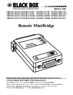
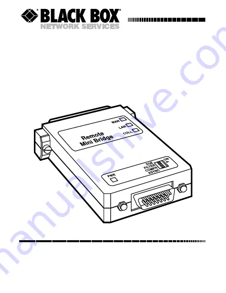
Remote MiniBridge

CUSTOMER SUPPORT INFORMATION

Order toll-free in the U.S.: Call 877-877-BBOX (outside U.S. call 724-746-5500)
FREE technical support 24 hours a day, 7 days a week: Call 724-746-5500 or fax 724-746-0746
Mailing address: Black Box Corporation, 1000 Park Drive, Lawrence, PA 15055-1018
Web site: www.blackbox.com •   E-mail: [email protected]

Summary of Contents for LB0010A-A21-R2

Page 1: ...0010A U35 R2 LB0010A U530 R2 LB0010A U4W R2 LB0010A USST R2 Remote MiniBridge CUSTOMER SUPPORT INFORMATION Order toll free in the U S Call 877 877 BBOX outside U S call 724 746 5500 FREE technical support 24 hours a day 7 days a week Call 724 746 5500 or fax 724 746 0746 Mailing address Black Box Corporation 1000 Park Drive Lawrence PA 15055 1018 Web site www blackbox com E mail info blackbox com ...

Page 2: ... is operated in a commercial environment Operation of this equipment in a residential area is likely to cause interference in which case the user at his own expense will be required to take whatever measures may be necessary to correct the interference Changes or modifications not expressly approved by the party responsible for compliance could void the user s authority to operate the equipment Th...

Page 3: ...imits and methods of measurement of radio disturbance characteristics of information technology equipment EN50082 1 1992 Electromagnetic compatibility Generic immunity standard for residential commercial and light industry The Remote MiniBridge herewith complies with the requirements of the EMC Directive 89 336 EEC The product was tested in a typical configuration ...

Page 4: ...abo sótano mojado o cerca de una alberca etc 6 El aparato eléctrico debe ser usado únicamente con carritos o pedestales que sean recomendados por el fabricante 7 El aparato eléctrico debe ser montado a la pared o al techo sólo como sea recomendado por el fabricante 8 Servicio El usuario no debe intentar dar servicio al equipo eléctrico más allá a lo descrito en las instrucciones de operación Todo ...

Page 5: ...s contactos y receptáculos donde salen del aparato 14 El equipo eléctrico debe ser limpiado únicamente de acuerdo a las recomendaciones del fabricante 15 En caso de existir una antena externa deberá ser localizada lejos de las lineas de energia 16 El cable de corriente deberá ser desconectado del cuando el equipo no sea usado por un largo periodo de tiempo 17 Cuidado debe ser tomado de tal manera ...

Page 6: ...ly with a UL listed and CSA Certified Class 2 power supply rated 12 VDC 400 or more mA Exigences UL INSTRUCTIONS IMPORTANTS DE SÉCURITÉ Pour les utilisateurs Nord Americains Le MiniBridge Remote est renforcé par un transformateur extérieur Afin de réduire le risque d électrocution de feux ou de blessure utiliser seulement avec le UL listé et le CSA Certifié classe 2 le transformateur de 12 VDC 400...

Page 7: ...nly with a power supply which is approved for the latest version of EN 60950 TÜV Zertifizierungsanforderungen Europäische Benutzer Leistungsaufnahme 12 VDC 400 oder mehr mA ACHTUNG Um das Risiko eines elektrischen Schlages oder Brandes so weit wie möglich zu vermeiden verwenden Sie nur ein Stromversorgung das gemäß der neuesten Version des Standards EN 60950 zugelassen ist ...

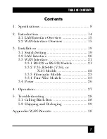
Page 8: ...stallation 19 3 1 Switch Setting 19 3 2 LAN Interface 20 3 3 WAN Interface 21 3 3 1 RS 232 or RS 530 Models 21 3 3 2 V 35 RS 449 V 36 or X 21 Models 22 3 3 3 Fiberoptic Models 23 3 3 4 Four Wire Models 23 3 4 Power 26 4 Operation 27 5 Troubleshooting 28 5 1 Calling Black Box 28 5 2 Shipping and Packaging 29 Appendix WAN Pinouts 30 ...

Page 9: ...models ITU TSS V 35 x36 models TIA RS 422 ITU TSS V 36 x53 models TIA RS 530 x21 models ITU TSS X 21 x4W models Proprietary 4 wire xMST models 850 nm multimode fiberoptic xSST models 1300 nm single mode fiberoptic Protocols WAN Synchronous or asynchonous embedded in RFC 1662 variant of HDLC framing LAN Table 10 000 MAC addresses with five minute automatic aging updating Filtering and Forwarding 14...

Page 10: ...t bit and followed by a stop bit Flow Control None Operation LAN AUI models Half duplex 10BASE T models Half or full duplex Data Rate LAN Full duplex 10BASE T 20 Mbps AUI or regular 10BASE T 10 Mbps WAN Synchronous Up to 10 Mbps Asynchronous all except 4 wire and fiberoptic models 115 2 57 6 38 4 28 8 19 2 14 4 or 9 6 Kbps user selectable but see Section 2 2 Clock Source WAN External only ...

Page 11: ... WAN x4W models 700 m 2296 ft over Category 5 or screened shielded Category 3 cable at 5 Mbps see Sections 3 1 and 3 3 4 xMST models Approx 3 km 1 8 mi depending on fiber quality xSST models Approx 20 km 12 4 mi depending on fiber quality All other models Standard maximum distance for given interface User Controls 1 Top mounted 4 position DIP switch for filtering compression either SQE AUI models ...

Page 12: ...green while unit is powered Connectors LAN Models with Axx product code suffix DB15 male Models with Uxx product code suffix Shielded RJ 45 female WAN x24 models DB25 female x35 models DB25 female proprietarily pinned for V 35 patch cable to M 34 included x36 models DB25 female pinned for TIA RS 530 patch cable to DB37 included x53 models DB25 female x21 models DB25 female pinned for TIA RS 530 pa...

Page 13: ...TBF 506 000 hours Temperature Tolerance 32 to 122 F 0 to 50 C Humidity Tolerance Up to 90 noncondensing Power From desktop autosensing power supply Input 100 to 250 VAC 50 to 60 Hz Output 12 VDC at least 400 mA Consumption Fiberoptic models 300 mA 3 6 watts typical 400 mA 4 8 watts maximum All other models 200 mA 2 4 watts typical 400 mA 4 8 watts maximum Size Fiberoptic models 0 7 H x 2 1 W x 3 D...

Page 14: ...13 CHAPTER 1 Specifications Weight Fiberoptic models 1 6 oz 50 g All other models 1 oz 30 g ...

Page 15: ...cally learns MAC addresses on the LAN to which it is connected and only forwards frames destined for another LAN Its LAN table stores up to 10 000 addresses and is automatically updated Filtering and forwarding is performed at 14 880 pps packets per second just shy of the maximum theoretical wire speed rate of 15 000 pps The RMB s buffer can hold 256 frames with a throughput latency of 1 frame Alt...

Page 16: ... the RMB is attached doesn t provide an adequate amount of power use the included external power supply to override the AUI supply On all models you can disable the Ethernet SQE test for hub or repeater connections 2 2 WAN Interface Overview The Remote MiniBridge is also available with any of eight WAN interfaces TIA RS 232 ITU TSS V 24 V 28 ITU TSS V 35 TIA RS 422 449 ITU TSS V 36 TIA RS 530 ITU ...

Page 17: ...e RMB to communicate asynchronously at 4800 bps the device attached to its WAN side has to provide a sync signal at 4800 x 16 76 800 bps on Pin 15 Table 2 1 Grounding for asynchronous control Data Rate or DB25 Pin 6 DB25 Pin 8 DB25 Pin 17 DB25 Pin 22 Feature Grounded Grounded Grounded Grounded Follow ext clock Yes Yes Yes N A sync on Pin 15 115 2 Kbps Yes Yes No N A 57 6 Kbps Yes No Yes N A 38 4 K...

Page 18: ...0x7D or other single octet in its Async Control Character Map ACCM with two octets the control escape octet followed by the original octet XORed with 0x20 The ACCM consists of the first 32 characters in the ASCII character set those with octet values up to 0x20 You can disable ACCM octet stuffing by tying Pin 22 of the RMB s DB25 connector to ground refer to Table 2 1 on the previous page If you w...

Page 19: ... and power see Chapter 4 The unit has four conveniently located DIP switches for easy configuration see Section 3 1 A typical application for the Remote MiniBridge is shown in Figure 2 1 below Figure 2 1 A Remote MiniBridge application Stackable Ethernet Hub Remote MiniBridge Modem Modem Remote MiniBridge Ethernet Switch ...

Page 20: ...l either plug it directly into the DTE s AUI port or attach it to the DTE s AUI port with a standard AUI cable If your Remote MiniBridge is a 10BASE T model use either a straight through pinned or cross pinned cable to attach the unit to a device s 10BASE T port Run straight through cable to connect the RMB to a hub or similar device Run cross pinned cable to connect the RMB to a NIC workstation o...

Page 21: ...the RMB transmit all frames that it receives across the WAN Disable filtering for LAN extender or segmenter applications COMPR ON Set to ON on the RMBs at both ends of a WAN link to activate compression The RMBs strip the padding bits from frames they transmit across the link in order to improve throughput Set to OFF to disable compression Set COMPR OFF when you have a Remote MiniBridge on one end...

Page 22: ...e gender changer A DTE device You will need a special cable that a has a DB25 male connector on the RMB end b has a connector that can mate with the DTE s serial port connector on the DTE end and c is cross pinned like a null modem cable but carries any necessary clock signal from the DTE call for technical support if you need such a cable Securely attach this cable to the RMB s WAN connector and ...

Page 23: ...der changer between them A DTE device You will either need to run both the included adapter cable and a special cross pinned cable see the DTE device paragraph on the previous page between RMB and the device s serial port or you will need a special adapter cable that performs both of these functions Call Black Box for technical support Refer to the Appendix for the pinouts of the RMB s WAN connect...

Page 24: ...connector on the other RMB 3 3 4 FOUR WIRE MODELS Run 4 wire twisted pair cabling between your Remote MiniBridges Keep these distance data rates in mind If you set the RMB s top panel LONG switch to OFF The RMB will transmit across the WAN link at 10 Mbps and you can run CAT5 or shielded screened CAT3 cable as far as 500 m 1640 ft CAT3 UTP as far as 400 m 1312 ft If you set the LONG switch to ON T...

Page 25: ...nish this procedure The RMB could be damaged and you could suffer a dangerous electrical shock Figure 3 1 Attaching the cable to a 4 wire RMB 1 Slip the included protective strain relief boot over the end of the wire skinny end first and slide it a few inches up the wire Terminal Block Screw Terminals One Wire Pair One Wire Pair Shield One End Only TX RX TX RX FGND ...

Page 26: ...ck s TX and TX left hand terminals and screw them down securely Fasten the other pair to the RX and RX right hand terminals the same way Make sure that TX and TX on each RMB are connected to RX and RX respectively on the other RMB If the cable is shielded you can connect the shield to the FGND center terminal of one RMB only Do not attach the shield to the FGND terminals of both RMBs this could ca...

Page 27: ... output cable of the unit s power supply into its power jack If your RMB is an AUI model you might not need to use the external power supply see Section 2 1 Then plug the power supply s input cable into the utility mains outlet If the RMB s PWR LED lights as it should the unit is ready for continuous operation ...

Page 28: ...ously lit On 10BASE T models the green LAN LED should be continuously lit if the 10BASE T link between the RMB and the attached device is OK The RMB s yellow WAN and LAN LEDs may blink occasionally or be continuously lit depending on the amount of data traffic The COLL LED should blink occasionally If you ever need to change the settings of the RMB move its top mounted four position configuration ...

Page 29: ... might be solvable over the phone Before you call make a record of the history of the problem We will be able to provide more efficient and accurate assistance if you have a complete description including the nature and duration of the problem when the problem occurs the components involved in the problem any particular application that when used appears to create the problem or make it worse and ...

Page 30: ... MiniBridge Package it carefully We recommend that you use the original container If the shipping is return or repair related pack the RMB its power supply and this manual together Contact Black Box to get a Return Materials Authorization RMA number CHAPTER 5 Troubleshooting ...

Page 31: ...t for the DB25 connector but they include adapter cables that patch the leads signals shown in the RS 530 column to the matching leads signals on DB37 and DB15 connectors respectively these are the pins listed in the same row in the RS 449 and X 21 columns The V 35 models use the proprietary pinout shown in the V 35 DB25 column but they include an adapter cable that patches this to an M 34 connect...

Page 32: ...nes marked N A instead of n BAUDX or n ACCM in the table s X 21 and V 35 M 34 columns aren t available on the adapter cable s native X 21 and V 35 connectors This means that if you need to run at certain data rates or turn off the Async Control Character Map you might have to build a cable directly to the RMB s DB25 connector in order to ground these leads ...

Page 33: ... out S 104 3 RD in 3 RD A in 6 RD A in 4 R A in 3 RD A in R N A 16 RD B in 24 RD B in 11 R B in 16 RD B in T 105 4 RTS out 4 RTS A out 7 RS A out 3 C A out 4 RTS out C N A 19 RTS B out 25 RS B out 10 C B out N A 106 5 CTS in 5 CTS A in 9 CS A in N A 5 CTS in D N A 13 CTS B in 27 CS B in N A N A N A 6 BAUD2 6 BAUD2 11 BAUD2 N A 6 BAUD2 E N A 8 BAUD1 8 BAUD1 13 BAUD1 5 BAUD1 8 BAUD1 F 114 15 TCLK in...

Page 34: ... ITU T RS 232 RS 530 RS 449 X 21 V 35 V 35 V 24 DB25 M 34 CIRC 115 17 RCLK in 17 RCLK A in 8 RT A in N A 17 SCR A in V sync N A 9 RCLK B in 26 RT B in N A 9 SCR B in X asy 17 BAUD0 17 BAUD0 8 BAUD0 N A 17 BAUD0 V N A 22 ACCM 22 ACCM 29 ACCM N A 22 ACCM N A ...

Page 35: ...34 REMOTE MINIBRIDGE TRADEMARK USED IN THIS MANUAL ST is a registered trademark of AT T Any other trademarks mentioned in this manual are acknowledged to be the property of the trademark owners ...

Page 36: ...NOTES ...

Page 37: ...NOTES ...

Page 38: ...1000 Park Drive Lawrence PA 15055 1018 724 746 5500 Fax 724 746 0746 Copyright 1999 Black Box Corporation All rights reserved ...

Reviews: