background image

ServView CX Rack Tray

724-746-5500   |   blackbox.com 

Page 12

3.3 Connecting the rack tray

All server, network and power connections are located at the rear of the unit.

3.3.1 The EXTernal link (network or remote user)

The single RJ-45 socket labeled as 

EXT

 is used to allow either global or remote users to login and control connected servers. The 

EXT port provides one of the following links (dependant on the model of rack tray):

•  An ethernet network link, labeled 

,

   or 

•  A remote extender link (to attach a ServSwitch CX Remote USB), labeled 

KVM

only

. Note: This port is NOT a network port. 

3.3.1.1 Connecting the external link

1  Wherever possible, ensure that power is disconnected from the rack tray. 

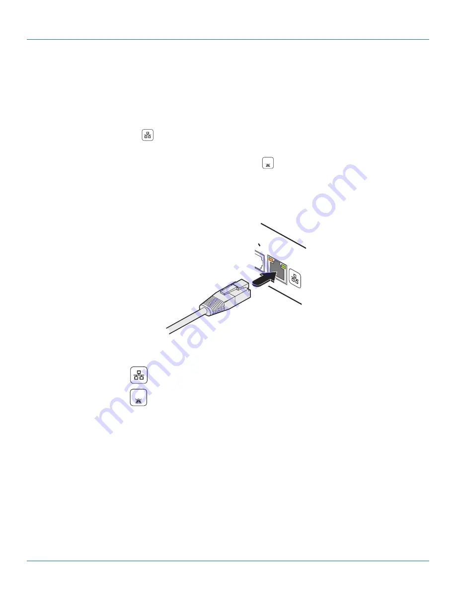
2  Connect a CAT 5, 5e or 6 link cable to the port labeled EXT. See Figure 3-4.

Link cable from either a net-
work connection or a remote 
extender 

EX

T

Figure 3-4. Connecting a CAT 5, 5e or 6 link cable to the EXT port.

3  Connect the other end of the cable as follows:

•  If the EXT port label shows 

 connect the link cable to a network switch/router.

•  If the EXT port label shows 

KVM

only

 connect the link cable to a Black Box ServSwitch CX Remote USB extender.

Summary of Contents for KKVTA174UK-16

Page 1: ...ServView CX Rack Tray KVTA170UK 16 KVTA171UK 16 KKVTA174UK 16 Order toll free in the U S Call 877 877 BBOX outside U S call 724 746 5500 FREE technical support 24 hours a day 7 days a week Call 724 7...

Page 2: ...e is a registered trademark of Novell Inc Sun is a trademark of Sun Microsystems Inc Unix is a registered trademark of UNIX System Laboratories Inc BSD is a registered trademark of UUNet Technologies...

Page 3: ...en the equipment is operated in a commercial environment Operation of this equipment in a residential area is likely to cause interference in which case the user at his own expense will be required to...

Page 4: ...pidan el flujo de aire por los orificios de ventilaci n 10 El equipo el ctrico deber ser situado fuera del alcance de fuentes de calor como radiadores registros de calor estufas u otros aparatos inclu...

Page 5: ...he EXTernal link network or remote user 12 3 3 2 Server access module links 13 3 4 Power Connection 14 4 Configuration 15 4 1 Initial Configuration 15 5 Operation 16 5 1 Opening and closing the rack t...

Page 6: ...ls CE FCC Software Compatibility Operates with all known software and operating systems including Windows Linux Unix BSD all Sun OS all Mac OS NetWare etc Operating Temperature 32 to 104 F 0 to 40 C P...

Page 7: ...other Black Box user guides for details about the KVM module fitted within your rack tray These other guides are stored on the CD ROM supplied with your rack tray and are also available at the Black...

Page 8: ...If anything is missing or damaged contact Black Box at 724 746 5500 or info blackbox com ServView CX rack tray assembly Left and right mounting brackets 8 x screws and cup washers 6 x cage nuts Power...

Page 9: ...Modules PS 2 style Analog video PS 2 style keyboard and PS 2 style mouse Part code KV1400A USB Analog video USB keyboard and mouse Part code KV1401A Sun Analog video Sun keyboard and mouse plus 3 5mm...

Page 10: ...ration Position the rack tray with respect to related facilities 3 2 Mounting the rack tray 1 Determine the appropriate position for the rack tray within your rack frame Insert two of the supplied cag...

Page 11: ...ils 5 Return the LCD keyboard drawer to park position 6 Use the remaining two M6 screws and cup washers to fix the front mounting ears of the rack tray assembly to rack rails See Figure 3 3 3 Insert t...

Page 12: ...e extender link to attach a ServSwitch CX Remote USB labeled KVM only Note This port is NOT a network port 3 3 1 1 Connecting the external link 1 Wherever possible ensure that power is disconnected fr...

Page 13: ...oes not exceed 300 metres 980 feet 1 Wherever possible ensure that power is disconnected from the rack tray 2 Connect a CAT 5 5e or 6 link cable to one of the COMPUTER CONNECTIONS ports See Figure 3 5...

Page 14: ...to the rear panel power socket 2 Connect the IEC connector of the supplied country specific power lead to the socket of the power adapter 3 Connect the power cord to a nearby power outlet Note Both t...

Page 15: ...epend on the model being used For more information please refer to the Configuration section of the appropriate ServSwitch user guide as appropriate to the KVM module being used KVTA170UK 16 use ServS...

Page 16: ...and gently pull the carry handle towards you See Figure 5 1 Figure 5 1 Press the release button and pull the rack tray 2 Once the drawer is fully extended lift up the carry handle to reveal the scree...

Page 17: ...gure 5 3 Figure 5 3 Locate the release buttons on each side 2 Pull forward and hold the two black arrow buttons while slightly pushing the drawer slider in to release the locks 3 Gently push the drawe...

Page 18: ...reen See Figure 5 5 Power indicator green on orange power saving mode Power button for the screen Display the OSD menu for the screen Scroll buttons to control OSD menus for the screen To auto adjust...

Page 19: ...nels In operation you can select server channels in two main ways including On screen menu this is different to the OSD for the screen or Keyboard hotkeys For more information please refer to the Oper...

Page 20: ...nsure that the power adaptor is mounted so that neither its cables nor connectors are stressed Observe all precautions and warnings attached to the equipment Warning live parts contained within power...

Page 21: ...een specifications The following specifications apply to both screen sizes unless indicated otherwise Maximum resolution 1280x 1024 Brightness 300 Cd m2 Contrast ratio 1000 1 Viewing angle 160o x 160o...

Page 22: ...power and surge protection products to media converters and Ethernet switches all supported by free live 24 7 Tech support available in 30 seconds or less Copyright 2011 Black Box Corporation All righ...

Reviews: