background image

37

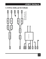
C.2 IC473A, IC630A, and IC631A Models

TRANSMITTED DA

T

A

CLAMPED 

T

O

 1v p–p

OUTPUT

BUFFER

SURGE

PROTECTION

SURGE

PROTECTION

SURGE

PROTECTION

SURGE

PROTECTION

OUTPUT

BUFFER

ACTIVE

FIL

TER

SCHMITT

TRIGGER

RCV+

RCV–

GND

XMT–

XMT+

5

3

2

1

4

>

>

>

>

>

>

>

>

>

>

>>

SG

DSR

TD

DTR

CD

CTS

RT

S

TD

RD

3

D

ATA

2

7

1

4

3

6

5

8

–V

+V

POWER SUPPL

Y

+V

APPENDIX C: Block Diagrams

NOTE: The RCV+ line is held

negative with respect to RCV–

when no data is being received.

Summary of Contents for IC470A

Page 1: ...1000 Park Drive Lawrence PA 15055 1018 724 746 5500 Fax 724 746 0746 Copyright 2000 Black Box Corporation All rights reserved ...

Page 2: ...Interface Converters CUSTOMER SUPPORT INFORMATION Order toll free in the U S Call 877 877 BBOX outside U S call 724 746 5500 FREE technical support 24 hours a day 7 days a week Call 724 746 5500 or fax 724 746 0746 Mailing address Black Box Corporation 1000 Park Drive Lawrence PA 15055 1018 Web site www blackbox com E mail info blackbox com RS 232 RS 422 Converter ...

Page 3: ...tial area is likely to cause interference in which case the user at his own expense will be required to take whatever measures may be necessary to correct the interference Changes or modifications not expressly approved by the party responsible for compliance could void the user s authority to operate the equipment This digital apparatus does not exceed the Class A limits for radio noise emission ...

Page 4: ... RS 422 INTERFACE CONVERTERS DECLARATION OF CONFORMITY This equipment has been tested and found to comply with the European Union s Electromagnetic Compatibility EMC directive and its Low Voltage Directive LVD ...

Page 5: ...abo sótano mojado o cerca de una alberca etc 6 El aparato eléctrico debe ser usado únicamente con carritos o pedestales que sean recomendados por el fabricante 7 El aparato eléctrico debe ser montado a la pared o al techo sólo como sea recomendado por el fabricante 8 Servicio El usuario no debe intentar dar servicio al equipo eléctrico más allá a lo descrito en las instrucciones de operación Todo ...

Page 6: ...ión a los contactos y receptáculos donde salen del aparato 14 El equipo eléctrico debe ser limpiado únicamente de acuerdo a las recomendaciones del fabricante 15 En caso de existir una antena externa deberá ser localizada lejos de las lineas de energia 16 El cable de corriente deberá ser desconectado del cuando el equipo no sea usado por un largo periodo de tiempo 17 Cuidado debe ser tomado de tal...

Page 7: ...n to an RJ 12 IC630A Models or RJ 45 IC631A Models 16 4 1 3 Making an RS 422 Connection to a 5 Position Terminal Block IC470A and IC473A Models 19 4 2 Connecting Devices or Cables to the RS 232 Interface 27 5 Operation 28 6 Troubleshooting 29 6 1 Calling Black Box 29 6 2 Shipping and Packaging 30 Appendix A Cable Guidelines 31 Appendix B RS 232 Pinouts 33 B 1 Pinout on DB25 IC470A through IC472A M...

Page 8: ...ning on DB25 IC473A IC630A and IC631A models Pinned according to TIA 574 on DB9 To line EIA TIA RS 422 or IC471 and IC472 models only RS 530 transmit and receive data signals only Protocol Asynchronous Data Format Transparent to data format Flow Control Transparent to software flow control X ON X OFF etc loops back RS 232 hardware flow control signals RTS CTS DTR DSR and CD Operation 4 wire transp...

Page 9: ...t setting is DCE Indicators None Connectors All end mounted RS 232 IC470A F IC471A F IC472A F 1 DB25 female IC470A M IC471A M IC472A M 1 DB25 male IC473A F IC630A F IC631A F 1 DB9 female IC473A M IC630A M IC631A M 1 DB9 male RS 422 IC470A and IC473A models 1 5 position terminal block IC630A models 1 RJ 12 6 wire RJ 11 female IC631A models 1 RJ 45 female RS 422 530 IC471A models 1 DB25 female IC472...

Page 10: ...10 000 ft 3048 m Temperature Tolerance 32 to 140 F 0 to 60 C Humidity Tolerance Up to 95 noncondensing Enclosure ABS plastic Size IC470A IC471A and IC472A models 2 2 H x 1 8 W x 0 8 D 5 6 x 4 5 x 1 9 cm IC473A IC630A and IC631A models 2 5 H x 1 2 W x 0 8 D 6 4 x 3 x 1 9 cm Weight IC470A IC471A and IC472A models 2 oz 57 g IC473A IC630A and IC631A models 3 oz 85 g ...

Page 11: ...tion from the data and control voltages on the RS 232 interface They perform full duplex bidirectional data conversion at RS 422 530 distances up to 4000 feet 1219 m Some converter models the IC473A IC630A and IC631A models have DB9 RS 232 connectors for easy attachment to the current generation of computers and serial cables The other Converter models IC470A through IC472A models have DB25 RS 232...

Page 12: ...n 5 position terminal blocks strain relief included IC630A models carry it on RJ 12 6 wire RJ 11 jacks and IC631A models carry it on RJ 45 jacks The IC471A and IC472A models carry either RS 422 or the transmit and receive data leads of RS 530 on DB25 female and DB25 male connectors respectively 2 2 Features and Benefits Bidirectionally convert RS 232 signals to balanced RS 422 signals or RS 530 tr...

Page 13: ...ction Data rates to 19 200 bps RS 422 530 distances to 4000 ft 1219 m Powered through its RS 232 interface Extremely compact Models available with a variety of RS 422 530 connectors and either DB25 or DB9 RS 232 connectors ...

Page 14: ...S 232 on DB25 connectors IC470A IC471A and IC472A models as DTE or DCE using their external DTE DCE switch The IC473A IC630A and IC631A models which carry RS 232 on DB9 are always DCE and have no such switch Refer to Figure 3 1 on the next page If you ll be plugging the Converter into a DTE such as a computer terminal or serial printer make sure the Converter s DTE DCE switch is in the complementa...

Page 15: ...13 Figure 3 1 The DTE DCE switch on the IC470A IC471A and IC472A models of the Converter DCE DTE CHAPTER 3 Configuration RS 232 Connector Other end has RS 422 530 connector terminal block or DB25 ...

Page 16: ...able such as our product code EYN712A should do fine IMPORTANT NOTE Please be aware as you run RS 422 cable from the Converter to the RS 422 device that the Converter s polarity might be the reverse of the device s If connecting to and to doesn t work try connecting to and to Different models of the Converter have different RS 422 and RS 530 interface connectors IC470A and IC473A models have a 5 p...

Page 17: ...ave DB25 female and DB25 male RS 422 530 connectors respectively These are pinned according to RS 530 although only the transmit and receive data signals are supported When you run cable from the Converter to another RS 422 or RS 530 device make sure the cable is pinned as shown below with the XMT RCV wires in one pair and the RCV XMT wires in another pair RS 530 DB25 RS 422 RS 422 DB25 RS 530 Sig...

Page 18: ... RJ 45 female RS 422 connectors respectively These are pinned in a USOC style for a standard telco wiring environment as shown below IC630A IC631A RJ 12 RJ 45 Lead Pin Pin Signal 1 N C 1 2 GND 2 3 RCV 3 4 XMT 4 5 XMT 5 6 RCV 6 7 GND 8 N C You don t have to connect the GND ground pins to anything ground connections are strictly optional although you can connect a cable shield to ground at one end o...

Page 19: ...ck 5 RCV XMT 4 Red Yellow 2 RCV RCV 5 Black Green 3 XMT RCV 2 Yellow Red 4 XMT If the cable is shielded you can attach one end of the shield to GND ground Pin 1 or Pin 6 Do not run wire from a ground at one end of the cable to a ground at the other end the Converter does not reference ground for RS 422 data transmission and you could create an electrical ground loop that could severely damage your...

Page 20: ...und at one end of the cable to a ground at the other end the Converter does not reference ground for RS 422 data transmission and you could create an electrical ground loop that could severely damage your equipment Also remember that Pins 1 and 8 are not connected to anything inside the Converter so do not connect any wires to them These are standard AT T color codes The RJ 45 connectors on your c...

Page 21: ...ct the wires to the block and fasten a strain relief collar in place so that the wires won t pull loose Take these steps 1 Open the unit by gently inserting a screwdriver between the DB25 or DB9 connector and the lip of the plastic case as shown below and at the top of the next page You don t have to worry about breaking the plastic but be careful not to bend the connector Once you ve opened the u...

Page 22: ...422 INTERFACE CONVERTERS 2 Strip the jacket and outer insulation from the last inch or so 2 5 cm of the twisted pair cable 3 Strip the insulation from the last quarter inch or so 0 6 cm of each of the cable s wires ...

Page 23: ...the ordering of the terminals is reversed in the IC473A M as opposed to the IC473A F and the IC470A models Note that when you connect the cable at the other end you ll want to cross pin the wires this way with the XMT RCV wires in one pair and the RCV XMT wires in another pair Converter RS 422 Device XMT A RCV XMT B RCV RCV A XMT RCV B XMT RCV G XMT A B B A XMT G RCV A B B A CHAPTER 4 Installation...

Page 24: ...le This is strictly optional the Converter doesn t require that you use shielded cable or a cable with a ground wire to operate properly Do not connect a cable shield or a ground wire to ground at both ends of the RS 422 cable The Converter does not reference ground for RS 422 data transmission and you could create an electrical ground loop that could severely damage your equipment ...

Page 25: ...nverter assembly should resemble the appropriate illustration below Here and throughout the rest of this section the two types of Converter models are not shown to scale with each other XMT G RCV A B B A XMT G RCV A B B A CHAPTER 4 Installation IC470A models IC473A models ...

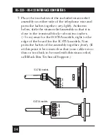
Page 26: ...ief assembly so that it is close to the terminal block about two inches 5 cm away for the IC470A models right to the edge of the board for the IC473A models Now press the halves of the assembly together firmly If at this point it becomes clear that your cable is too thin or too thick to be used with this strain relief call Black Box Technical Support XMT G RCV A B B A XMT G RCV A B B A IC470A mode...

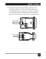
Page 27: ...th the wire going through it into the matching slot in the bottom half of the Converter case Set the whole circuit board cable end strain relief assembly back into the bottom of the case as shown below XMT G RCV A B B A XMT G RCV A B B A IC470A models IC473A models ...

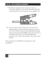
Page 28: ... together yet 10 The Converter comes with a pair of screws and saddle washers Put one of the washers on one of the screws Insert that screw through the matching hole on one side of the DB25 end of the case then snap that side of the case closed Repeat the process for the other side with the other screw and washer This completes your RS 422 terminal block cable installation ...

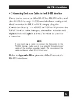
Page 29: ...r directly into a DB25 or DB9 serial port on the RS 232 device After doing so remember to insert and tighten the two captive screws screwlocks on the connector NOTE If you must use a cable to connect the Converter to the RS 232 device make sure it is a straight through pinned cable of the shortest possible length We recommend the cable not be more than 6 ft 1 8 m long Refer to Appendix B for pinou...

Page 30: ...ets its operating power from the RS 232 data and control signals it has no ON OFF switch so it will begin operating as soon as the RS 232 device powers up The Converter passes through all data signals from the RS 232 and RS 422 interfaces including any software flow control information It loops back all hardware flow control signals from the RS 232 interface it does not pass them It doesn t suppor...

Page 31: ...Support at 724 746 5500 Before you do make a record of the history of the problem We will be able to provide more efficient and accurate assistance if you have a complete description including the nature and duration of the problem when the problem occurs the components involved in the problem any particular application that when used appears to create the problem or make it worse and the results ...

Page 32: ...ng and Packaging If you need to transport or ship your Converter Package it carefully We recommend that you use the original container Before you ship the unit back to Black Box for repair or return contact us to get a Return Authorization RA number ...

Page 33: ... m 51 6 nF km or 49 9 pF m 22 AWG 83 nF mi or 15 7 pF ft 32 6 mΩ ft 107 mΩ m 51 6 nF km or 49 9 pF m 24 AWG 83 nF mi or 15 7 pF ft 51 7 mΩ ft 169 5 mΩ m 51 6 nF km or 49 9 pF m To get optimum performance from the Converter keep these guidelines in mind Always use twisted pair wire this is not an option Use twisted pair wire with a capacitance of 20 pF ft or less Avoid twisted pair wire thinner tha...

Page 34: ...g twisted pair cable with a resistance greater than that specified in this appendix might reduce the RS 422 530 distance you can run to below the normal maximum of 4000 ft 1219 m but the function of the Converter shouldn t be affected otherwise ...

Page 35: ...n 3 Receive Data RD When the Converter is set as DCE it receives data on Pin 2 and transmits on Pin 3 Two sets of RS 232 control signals RTS CTS and DTR DSR CD are jumpered together inside the Converter If the Converter receives Request to Send RTS on Pin 4 the Converter loops it back on the Clear to Send line CTS Pin 5 and vice versa If the Converter receives a control signal on either Data Termi...

Page 36: ...ame Ground FGND N A 2 Transmit Data TD OUT 3 Receive Data RD IN 4 Request to Send RTS OUT 5 Clear to Send CTS IN 6 Data Set Ready DSR IN 7 Signal Ground SGND N A 8 Carrier Detect CD IN IN Data Term Ready DTR 20 1 Frame Ground FGND N A 2 Transmit Data TD IN 3 Receive Data RD OUT 4 Request to Send RTS IN 5 Clear to Send CTS OUT 6 Data Set Ready DSR OUT 7 Signal Ground SGND N A 8 Carrier Detect CD OU...

Page 37: ...r If the Converter receives Request to Send RTS on Pin 7 the Converter loops it back on the Clear to Send line CTS Pin 8 and vice versa And if the Converter receives Data Terminal Ready DTR Pin 4 the Converter loops it back on the Carrier Detect line CD Pin 1 Also if the converter receives signals on any of these lines or on TD Pin 3 it emits a small positive voltage on the Data Set Ready DSR Pin ...

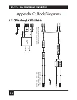
Page 38: ...UT BUFFER OUTPUT BUFFER TRANSMITTED DATA CLAMPED TO 3v p p XMT XMT DCE DTE SCHMITT TRIGGER ACTIVE FILTER RCV RCV GND SG FG 7 1 POWER SUPPLY V V DATA RTS 4 CTS 5 DSR 6 CD 8 20 DTR NOTE The directions of signal flow shown here are for a unit set to DCE NOTE The RCV line is held negative with respect to RCV when no data is being received ...

Page 39: ...URGE PROTECTION SURGE PROTECTION SURGE PROTECTION OUTPUT BUFFER ACTIVE FILTER SCHMITT TRIGGER RCV RCV GND XMT XMT 5 3 2 1 4 SG DSR TD DTR CD CTS RTS TD RD 3 DATA 2 7 1 4 3 6 5 8 V V POWER SUPPLY V APPENDIX C Block Diagrams NOTE The RCV line is held negative with respect to RCV when no data is being received ...

Page 40: ...NOTES ...

Reviews: