


12
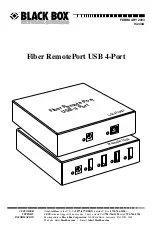
FIBER REMOTEPORT USB 4-PORT
3.3 Install the Local Unit
1. Place the local unit near the host computer you want to connect.
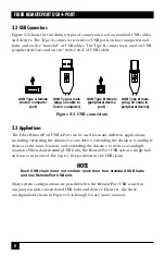
2. Plug the Type B connector on the included USB cable into the USB (host)
port on the local unit.
3. Plug the power supply’s input cord into a suitable working AC outlet.
4. Plug the power supply’s output cord into the local unit’s power jack.
5. Plug the Type A connector on the included USB cable into one of the USB
ports on the host computer.
3.4 Install the Remote Unit
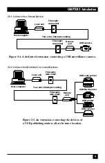
1. Place the remote unit near the USB peripheral device(s) you want to connect.
2. Connect each USB device to one of the USB (device) ports on the remote
unit. (Cables for this are not included.)
3. Plug the power supply’s input cord into a suitable working AC outlet.
4. Plug the power supply’s output cord into the remote unit’s power jack.
3.5 Interconnect the Two Units
NOTE
For proper operation, use only 62.5/125-µm or 50/125-µm multimode or
9/125-µm single-mode fiberoptic cable to interconnect the local and
remote units. The cabling must be duplex (have two fiber strands per
connection), must be terminated with MT-RJ connectors at both ends,
and must not be longer than 500 m (1640 ft.). For more information, see
the
Cable Required
specification in
Chapter 1
.
3.5.1 W
ITH
S
URFACE
(E
XPOSED
) C
ABLING
1. Plug one end of the fiberoptic cabling (not included) into the MT-RJ
connector on the local unit.
2. Plug the other end of the fiberoptic cabling into the MT-RJ connector on the
remote unit.
Summary of Contents for IC243A
Page 19: ...NOTES ...


