background image

1

FCC INFORMATION

FEDERAL COMMUNICATIONS COMMISSION

AND

INDUSTRY CANADA

RADIO FREQUENCY INTERFERENCE STATEMENTS

This equipment generates, uses, and can radiate radio frequency energy and if not installed and used
properly, that is, in strict accordance with the manufacturer’s instructions, may cause interference to radio
communication.  It has been tested and found to comply with the limits for a Class A computing device in
accordance with the specifications in Subpart J of Part 15 of FCC rules, which are designed to provide
reasonable protection against such interference when the equipment is operated in a commercial
environment.  Operation of this equipment in a residential area is likely to cause interference, in which case
the user at his own expense will be required to take whatever measures may be necessary to correct the
interference.

Changes or modifications not expressly approved by the party responsible for compliance could void the
user’s authority to operate the equipment.

This digital apparatus does not exceed the Class A limits for radio noise emission from digital apparatus set out in the
Radio Interference Regulation of Industry Canada.

Le présent appareil numérique n’émet pas de bruits radioélectriques dépassant les limites applicables aux appareils
numériques de classe A prescrites dans le Règlement sur le brouillage radioélectrique publié par Industrie Canada.

Summary of Contents for HS400A

Page 1: ...Pro Fit Mobile Headset HS400A ...

Page 2: ... operated in a commercial environment Operation of this equipment in a residential area is likely to cause interference in which case the user at his own expense will be required to take whatever measures may be necessary to correct the interference Changes or modifications not expressly approved by the party responsible for compliance could void the user s authority to operate the equipment This ...

Page 3: ...hone company may temporarily disconnect service 3 If you have problems with your telephone equipment after installing this device disconnect this device from the line to see if it is causing the problem If it is contact your supplier or an authorized agent 4 The telephone company may make changes in its technical operations and procedures If any such changes affect the compatibility or use of this...

Page 4: ...user s satisfaction Before installing this equipment users should ensure that it is permissible to be connected to the facilities of the local telecommunications company The equipment must also be installed using an acceptable method of connection In some cases the company s inside wiring associated with a single line individual service may be extended by means of a certified connector assembly ex...

Page 5: ...t exceed 100 NORMAS OFICIALES MEXICANAS NOM ELECTRICAL SAFETY STATEMENT INSTRUCCIONES DE SEGURIDAD 1 Todas las instrucciones de seguridad y operación deberán ser leídas antes de que el aparato eléctrico sea operado 2 Las instrucciones de seguridad y operación deberán ser guardadas para referencia futura 3 Todas las advertencias en el aparato eléctrico y en sus instrucciones de operación deben ser ...

Page 6: ...lor como radiadores registros de calor estufas u otros aparatos incluyendo amplificadores que producen calor 11 El aparato eléctrico deberá ser connectado a una fuente de poder sólo del tipo descrito en el instructivo de operación o como se indique en el aparato 12 Precaución debe ser tomada de tal manera que la tierra fisica y la polarización del equipo no sea eliminada 13 Los cables de la fuente...

Page 7: ...rvicio por personal calificado deberá ser provisto cuando A El cable de poder o el contacto ha sido dañado u B Objectos han caído o líquido ha sido derramado dentro del aparato o C El aparato ha sido expuesto a la lluvia o D El aparato parece no operar normalmente o muestra un cambio en su desempeño o E El aparato ha sido tirado o su cubierta ha sido dañada ...

Page 8: ...N THIS MANUAL TRADEMARKS USED IN THIS MANUAL UL is a registered trademark of Underwriters Laboratories Incorporated Any other trademarks mentioned in this manual are acknowledged to be the property of the trademark owners ...

Page 9: ...ile Flexible Earhook 11 3 2 Changing Ears 12 3 3 Removal 12 3 4 Installation 12 4 Earloop 13 4 1 Installation 13 4 2 Removal 13 4 3 Changing Ears 14 4 4 Wearing the Earloop 14 5 Headband 15 5 1 Installation 15 5 2 Removal 15 5 3 Changing Ears 16 5 4 Wearing the Headband 16 6 Microphone Positioning 17 7 Clothing Clip 18 8 Connecting to Your Telephone 19 9 Maintenance 20 10 Troubleshooting 21 ...

Page 10: ... 2 mA Operating voltage 1 4 to 10 VDC Sensitivity 1 kHz w 2 2 Kohm load 39 dBV Pa Receive Frequency Response 300 to 4000 Hz Input Impedance 150 ohms Speaker Dynamic Impedance 150 ohms Frequency Response 300 to 4000 Hz General Compliance Registered to UL 1459 FCC Part 68 registered OSHA Part 1910 subpart S CSA C22 2 No 225 M90 Weight 1 0 oz 28 3 g ...

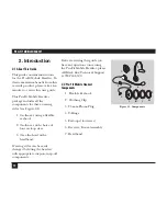
Page 11: ...exible earhook 2 On the ear with choice of four earloop sizes 3 Over the head with a headband Wearing styles can be easily changed by fitting the headset with appropriate snap on snap off components If after reviewing this guide you have any questions concerning the Pro Fit Mobile Headset please call Black Box Technical Support at 724 746 5500 2 2 Pro Fit Mobile Headset Components 1 Flexible Earho...

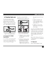
Page 12: ...the Earhook 1 Straighten out the earhook so that it points away from the speaker 2 Swing the hook away from the speaker and slide the Pro Fit Mobile earhook behind your ear until the saddle of the hook rests on the uppermost part of your ear 3 Adjust the flexible hook with your thumb until it rests comfortably along the back of the ear 4 Lightly press the speaker against the ear for proper positio...

Page 13: ...dex fingers wrapped around the swivel stem and the cable strain relief 3 Push your thumbs inward until the earhook pops free of the receiver 3 4 Installation 1 Remove the earloop or headband 2 Align the earhook mounting ring over the receiver with the swivel stem notch over the mounting post on the receiver see Figure 3 5 Figure 3 5 Earhook Assembly 3 With your fingers positioned behind the receiv...

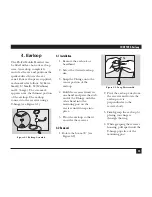
Page 14: ...arhook or headband 2 Select the desired earloop size 3 Snap the T hinge onto the center portion of the earloop 4 Hold the receiver firmly in one hand and press the stub end of the T hinge with the other hand into the mounting post on the receiver until it snaps into place 5 Pivot the earloop so that it encircles the receiver 4 2 Removal 1 Rotate the boom 90 see Figure 4 2 Figure 4 2 Loop Disassemb...

Page 15: ...posite ear 4 4 Wearing the Earloop 1 Swing the earloop away from the receiver to form a V see Figure 4 3 Figure 4 3 Earloop Wearing 2 Position the back of the earloop behind the ear and gently pull forward until the speaker rests on the ear Refer to the Microphone Positioning section Chapter 6 for additional information ...

Page 16: ... the boom turret 4 With your fingers behind the headband on the foam cushion use your thumbs to pop the headband onto the receiver 5 2 Removal 1 Hold the headband with the foam cushion facing you see Figure 5 2 Figure 5 2 Headband Removal 2 Position your fingers behind the outer portion of the headband mounting ring covered by the foam cushion 3 With your thumbs on the receiver push outward until ...

Page 17: ...ns and shortens to the desired length for a custom fit pull to lengthen push to shorten The headband retains its length and will not need adjusting each time it is put on The stabilizer cushion rests just above the ear on the side of your head opposite the speaker Figure 5 4 Headband Wearning Refer to the Microphone Positioning section Chapter 6 for additional information ...

Page 18: ...e rejects background noise and is better suited for noisy environments Position the microphone properly to take advantage of the noise canceling qualities of this microphone Your Pro Fit Mobile Headset has a flexible microphone boom The flexible boom can be reshaped until the microphone is correctly positioned in front of your mouth One hand should grasp and steady the receiver end of the boom The...

Page 19: ...stened for comfortable wearing see Figure 7 1 It is designed to prevent the weight of the cord from dislodging the headset Figure 7 1 Clothing Clip Position the clip conveniently on your clothing To reduce excess slack reposition the clip by sliding it up and down the cord ...

Page 20: ...directly into any mobile phone with this size port see Figure 8 1 Figure 8 1 Mobile Phone Connection For many mobile telephones without built in headset ports optional adapters are available see Figure 8 2 Figure 8 2 Mobile Phone Connection Using an Optional Adapter Call Black Box at 724 746 5500 for details Adapter not included 1 2 3 6 9 5 8 0 4 7 2 5 mm port ...

Page 21: ...harge can be passed through the headset to ground A user in close proximity to or touching the computer may feel a common shock sensation similar to touching a doorknob after walking across a carpet causing no harm to the user This discharge is entirely due to the computer monitor the headset is merely the shortest path to ground To minimize the possibility of electrostatic discharge through the h...

Page 22: ...a complete description including the nature and duration of the problem when the problem occurs the components involved in the problem any particular application that when used appears to create the problem or make it worse 10 2 Shipping and Packaging If you need to transport or ship your Pro Fit Mobile Headset Package it carefully We recommend that you use the original container If you are shippi...

Page 23: ...REE technical support 24 hours a day 7 days a week Call 724 746 5500 or fax 724 746 0746 Mailing address Black Box Corporation 1000 Park Drive Lawrence PA 15055 1018 Web site www blackbox com E mail info blackbox com Copyright 2000 Black Box Corporation All rights reserved 54 0218A June 2000 Printed in USA ...

Reviews: