background image

724-746-5500   |   blackbox.com 

Page 10

EC24U3032

Chapter 3: Mounting Instructions

3.3 Loading Equipment

WARNING: Only install equipment after the Elite Wallmount has been properly secured and mounted to the wall.

Maximum Load Capacity 

Rated or maximum load capacity for the Elite Wallmount:  

24"H = 150 pounds

36"H = 250 pounds

48"H = 300 pounds


3.4 Power

When using power distribution units (PDUs), each PDU should be connected to a committed branch circuit that is rated for the 
continuous load of all the equipment connected.

When not using a PDU, each piece of equipment should be connected to a dedicated branch circuit. 

3.5 Protective Grounding

A main protective earthing stud and grounding studs are provided.  

WARNING:  To avoid injury to persons or loss of life, ground each enclosure individually to the dedicated branch circuit earthing 

ground. 


3.5.1 Connecting Main Protective Grouding Stud to the Dedicated Branch Circuit Earthing Ground 

Conductor

Connect the dedicated branch circuit ground conductor to the main protective earthing stud located inside at the bottom rear of 
the enclosure chassis using a listed ring or closed-loop terminal.

3.5.2 Connecting Main Protective Grounding Stud to the Protective Bonding Conductors 

Connect the rear door to the main protective grounding stud located inside at the bottom rear of the enclosure chassis  
using a listed ring or closed-loop terminal. Connect the front door to the grounding stud located inside at the bottom front  
of the enclosure chassis using a listed ring or closed-loop terminal.    

Summary of Contents for EWM12U242418-R2

Page 1: ...0 or fax 724 746 0746 Mailing address Black Box Corporation 1000 Park Drive Lawrence PA 15055 1018 Web site www blackbox com E mail info blackbox com Customer Support Information EWM12U242418 R2 EWM20...

Page 2: ...to Black Box You ll be live with one of our technical experts in less than 60 seconds Trademarks Used in this Manual Black Box and the Double Diamond logo are registered trademarks and Elite is a trad...

Page 3: ...acking and Removing the Elite Wallmount Enclosure from the Pallet 9 3 2 Wood Studded Wall 9 3 3 Loading Equipment 10 3 4 Power 10 3 5 Protective Grounding 10 3 5 1 Connecting the Main Protective Groud...

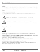
Page 4: ...caution could result in damage to equipment or storage data Safety Considerations WARNING Improper handling and use of the Elite Wallmount Cabinet could result in equipment damage serious injury or po...

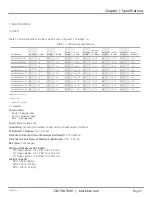
Page 5: ...8 23 8 EWM20U362430 R2 20 38 5 24 30 21 125 29 875 30 30 75 38 5 29 25 35 8 23 8 EWM26U482418 R2 26 49 24 18 21 125 41 875 18 18 75 49 17 25 47 8 23 8 EWM26U482424 R2 26 49 24 24 21 125 41 875 24 24...

Page 6: ...apter 1 Specifications Width 17 749 opening 18 312 centers Height One pair of adjustable mounting rails tapped 10 32 UNF 2B Figure 1 1 Front view doors removed for clarity Depth Depth see Table 1 1 7...

Page 7: ...Page 7 EC24U3032 Chapter 1 Specifications 3RU 4 75 18 31 10 00 Figure 1 3 Top view 16 00 10 00 9 00 Height see Table 1 1 9 00 Figure 1 4 Back view...

Page 8: ...What s Included Your package should include the following items If anything is missing or damaged please contact Black Box Technical Support at 724 746 5500 or info blackbox com Fully assembled Elite...

Page 9: ...ed routes and uneven floor surfaces may cause the enclosure to topple over 3 2 Wood Studded Wall Once the location on the wall has been determined inspect the wall surface The wall must be flat and sq...

Page 10: ...nd grounding studs are provided WARNING To avoid injury to persons or loss of life ground each enclosure individually to the dedicated branch circuit earthing ground 3 5 1 Connecting Main Protective G...

Page 11: ...hinge pins pull the door away from the enclosure To attach the door align both door hinges to their respective hinge pins on the enclosure and slowly slide the door down until seated 4 3 Reversing a D...

Page 12: ...vertical mounting rails is installed in all Elite Wallmount Cabinets Additional mounting rails are available as accessories Figure 4 2 Adjusting the vertical mounting rails Rails are attached using a...

Page 13: ...ounting 19 rackmount equipment such as patch panels and PDUs Vertical stationary rails in rear section tapped 10 32 Optional EWM90DAB R2 90 angle bracket Optional EWM45DAB R2 45 angle bracket kit 18 3...

Page 14: ...ose around cables to prevent unwanted airflow and keep dust and debris out Optional EC3UGP Gland Plate Kit Figure 5 3 Optional EC3UGP Gland Plate Kit Use the waterfall bracket to maintain bend radius...

Page 15: ...Page 15 EC24U3032 Use the vent cover plate to keep dust and debris from entering the cabinet EWMDCP R2 Vent Cover Plate Figure 5 5 EWMDCP R2 Vent Cover Plate Chapter 5 Optional Accessories Drawings...

Page 16: ...binets and racks and power and surge protection products to media converters and Ethernet switches all supported by free live 24 7 Tech support available in 60 seconds or less Copyright 2014 All right...

Reviews: