background image

63

1.877.877.2269

BLACKBOX.COM

NEED HELP?

LEAVE THE TECH TO US

LIVE 24/7

TECHNICAL

SUPPORT

1.877.877.2269

CHAPTER 5: CONFIGURING THE BUILT-IN NOTIFICATIONS

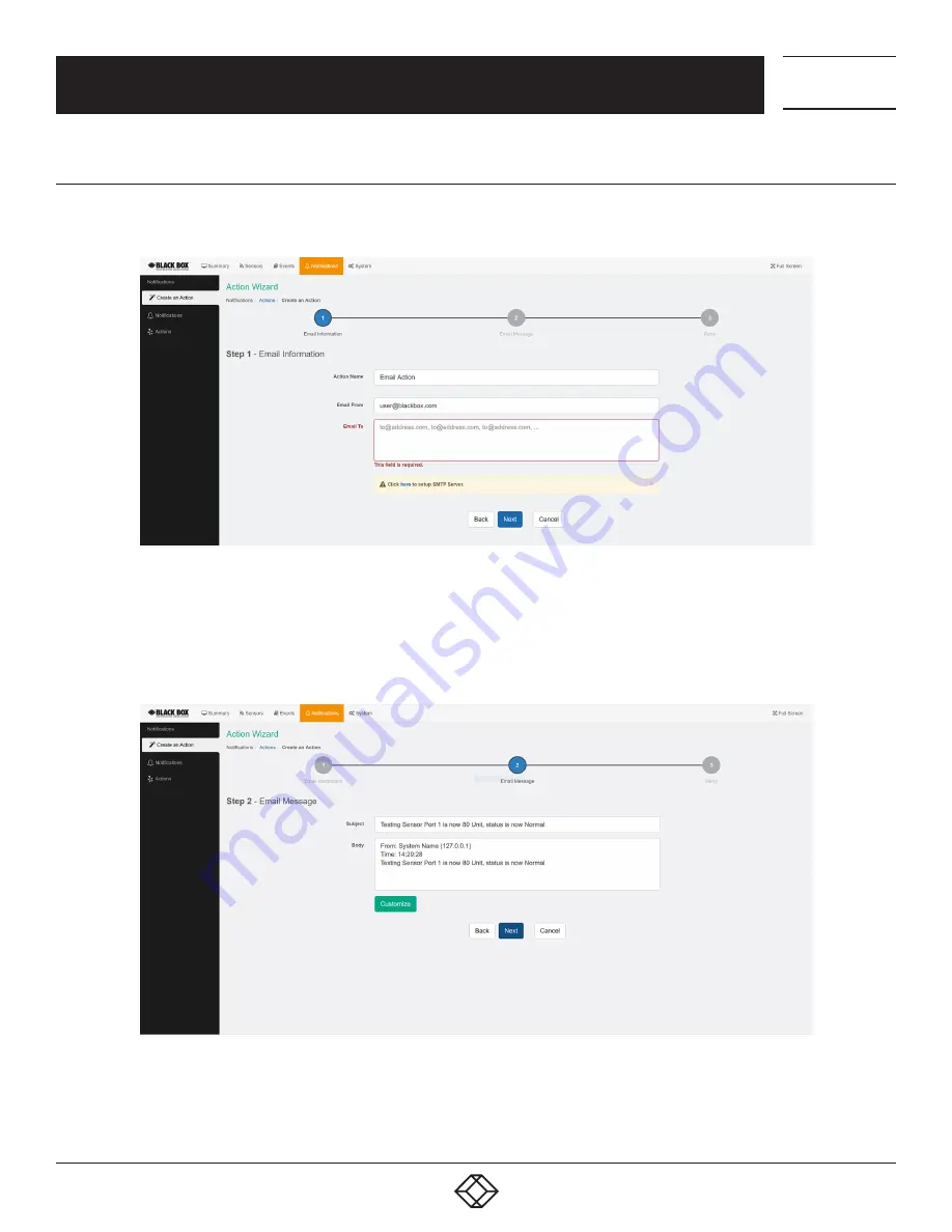
5.2.4 EMAIL ACTION SETUP 

You can use the Email Action to send a notification by email when a sensor reaches a certain threshold.

FIGURE 5-15. EMAIL INFORMATION

NOTE: The SMTP server settings needed to be configured on the unit before this action will work.

All email actions will use this SMTP server for sending emails.
Either click on the link on the notice, or go to the System/SMTP page for the configuration.

FIGURE 5-16. EMAIL MESSAGE

After clicking “Next,” you will get a page where you can input the email name and message. Press the “Customize” 
button and the fields will re-write in a format that will allow for an automated email that will display the sensor 
information.

Summary of Contents for EME160A

Page 1: ...24 7 TECHNICAL SUPPORT AT 1 877 877 2269 OR VISIT BLACKBOX COM ALERTWERKS GATEWAY 4 PORT EME160A EME160A UC EME161A R2 USER MANUAL ...

Page 2: ...ry IP Address to the Computer s LAN Card 10 4 WEB GRAPHICAL USER INTERFACE GUI 11 4 1 Summary Page 11 4 1 1 Graph Feature 13 4 2 System Page 15 4 2 1 General 15 4 2 2 Language Management 17 4 2 3 Date Time 22 4 2 4 Network 23 4 2 5 VPN 24 4 2 6 SMTP 25 4 2 7 SNMP 26 4 2 8 SNMPv3 27 4 2 9 Server Integration 28 4 2 10 Services 29 4 2 11 Modbus 31 4 2 12 Password Checking 33 4 2 13 Maintenance 34 4 2...

Page 3: ...rd 60 5 2 3 Dry Contact Action Setup 60 5 2 4 Email Action Setup 63 5 2 5 Relay Action Setup 65 5 2 6 Siren Action Setup 67 5 2 7 SMS Action Setup 69 5 2 8 SNMP Trap Action Setup 72 5 2 9 Telephone Call Action Setup 79 5 3 Example Notification Setup SMS Notification 82 5 4 Heartbeat Messages 86 5 5 Virtual Sensors 92 5 5 1 Boolean 93 5 5 2 SNMP Get 94 5 5 3 Virtual Ping 97 5 5 4 Logic 98 5 5 5 SNM...

Page 4: ...hese ports can carry configurable output signals 0 VDC 5 VDC Number of Users 100 Indicators 1 Power LED 1 Network Connectivity LED 4 Sensor Status LEDS 1 Buzzer for audible alert on sensor status Power 5 VDC 3 A Mounting Desktop Rackmounted or DIN rail mounted Max Sensors Maximum of 150 online sensors including Expansion Units and virtual sensors Operating Environment Temperature 13 to 176 F 25 to...

Page 5: ...ding SNMPv3 HTTPS VPN and MQTT Send encrypted SNMP Trap and Email Notifications Supports four Intelligent Sensors EME160A Two sensor ports enabled by default Unlock all four ports with unlock code EME160A UC Notification Wizards Wide range of available sensors Optional expansion module connectivity Virtual sensors NOTE Some of the pictures shown in this manual might not represent the actual Web UI...

Page 6: ... 5 m 1 CD Manual 2 4 HARDWARE DESCRIPTION 2 4 1 BACK PANEL PORTS Port numbering starts from the power connector on the unit the closest port to the power connector is Port 1 and closest to the Ethernet interface is Port 4 You may connect AlertWerks sensors to any available ports CAUTION If you re using analog pins on the sensor ports with manually on lined DCV sensors and pin 7 of the RJ 45 connec...

Page 7: ...le 2 2 describes their functions FIGURE 2 2 TOP PANEL STATUS LEDS TABLE 2 2 TOP PANEL COMPONENTS NUMBER IN FIGURE 2 2 COMPONENT DESCRIPTION 1 1 Power Ethernet ETH LED red green Turns red if there s no network connection and blinks green according to LAN activity when the connection is normal 2 4 Sensor LEDs 1 4 green Off offline On online and normal Slow blinking Warning status Fast blinking Criti...

Page 8: ...press Reset 1 2 FIGURE 2 3 SIDE PANEL TABLE 2 3 SIDE PANEL COMPONENTS NUMBER IN FIGURE 2 3 COMPONENT DESCRIPTION 1 Reset button Resets the gateway see Table 2 4 for functions 2 RJ 45 connector Links to Ethernet TABLE 2 4 RESET BUTTON FUNCTIONS TIME TO HOLD ACTION 3 to 7 seconds Reboot 7 to 12 seconds Web UI password reset 12 to 17 seconds Serial flash erase DB erase without factory reset the syste...

Page 9: ...ssover cable with an RJ 45 male connection A PC with Ethernet card or LAN socket logged in with Administrator rights Follow these steps 1 Connect the unit via the Ethernet port of the unit to your computer s LAN or Ethernet port with a CAT5 crossover cable 2 Open a web browser and type the default IP address then press enter 3 You ll be presented with the Summary page 4 Go to the System Network pa...

Page 10: ... SETTING SCREEN Or open an Administrator Command Prompt CMD window and type netsh interface ipv4 add address Local Area Connection 192 168 0 2 255 255 255 0 The above command adds the IP Address 192 168 0 2 with Subnet Mask 255 255 255 0 to the connection titled Local Area Connection You will then be able to connect to the unit with its default IP NOTE The secondary IP address is permanent for the...

Page 11: ... 1 shows the summary page FIGURE 4 1 SUMMARY PAGE This is the Summary page with Sensor Status and the Event Log with the Sensor Graph enabled The Event Log contains all entries from the All Events category The last 30 entries are shown but if you re scrolling down the list more events 30 more will be loaded automatically You can view the full log if you keep scrolling down ...

Page 12: ...PHICAL USER INTERFACE GUI FIGURE 4 2 SENSOR INFORMATION WINDOW In the Summary page s Sensors Information window you can do the following Directly acknowledge a sensor s status and put the sensor offline FIGURE 4 3 ACKNOWLEDGE SENSOR OR PUT IT OFFLINE Control the relay type sensors FIGURE 4 4 CONTROL THE RELAY TIME SENSORS ...

Page 13: ...eature in more detail next 4 1 1 GRAPH FEATURE After you ve enabled the data collection for a sensor you can choose to display specific time intervals of the stored data hourly daily weekly monthly and custom display interval You can also export the recorded data in multiple formats FIGURE 4 6 GRAPH FEATURE EXAMPLE In this example picture we ve chosen to display the temperature sensor s daily maxi...

Page 14: ...data in selected formats by clicking on the icon on the right The file will be downloaded automatically and assigned a file name that will contain the sensor s name IP address of the unit and the date and time FIGURE 4 8 LIVE GRAPH OPTION By choosing the Live Graph option you can get continuous updates of the graph data by default every 60 seconds If you don t use this option the graph data needs ...

Page 15: ... USER INTERFACE GUI FIGURE 4 9 SENSORS DROP DOWN MENU To change to a different sensor s graph choose it from the drop down menu NOTE You can only choose a sensor here that you ve already enabled the graph data collection for 4 2 SYSTEM PAGE Figure 4 1 shows the summary page 4 2 1 GENERAL FIGURE 4 10 SYSTEM PAGE GENERAL SETTINGS ...

Page 16: ... NOTE If you had stored graph data previously changing this setting will clear the data FIGURE 4 11 GRAPH DATA COLLECTION PERIOD SCREEN NOTE A Low Power Mode is selectable from EMEMS on the Web UI this option is not shown With the Sensor Notification On System Boot Up option you can choose to allow disallow running the notifications with sensor values read at system boot up In some cases invalid v...

Page 17: ... and in custom scripts or for setting up the unit for monitoring by a third party NMS software such as WhatsUpGold or Paessler This button is also accessible on the Sensors page 4 2 2 LANGUAGE MANAGEMENT FIGURE 4 14 LANGUAGE MANAGEMENT BUTTON You can change the display language of the Web UI with this option Only one additional language is supported together with the default and fallback if there ...

Page 18: ...d the completed file and it will be selectable as the Custom Language For official translation files the language code and version will show the correct values NOTE Whenever you upload or install a custom language file it will overwrite the old file Only one additional language is supported For separately downloadable language files contact Black Box Technical Support Select a language from the dr...

Page 19: ...he language is downloaded and installed FIGURE 4 18 INSTALLING LANGUAGE MESSAGE The unit will notify you about the successful language change and will change the language of the Web UI You can switch back to English by selecting it from the drop down list on the General page then press Save FIGURE 4 19 DROP DOWN LIST After you ve added the custom language you can manage it from the same menu ...

Page 20: ... SUPPORT 1 877 877 2269 CHAPTER 4 WEB GRAPHICAL USER INTERFACE GUI FIGURE 4 20 LANGUAGE SCREEN CUSTOM LANGUAGE NOTE The official language files are also included in the firmware update packages You can also edit the chosen language directly in the Web UI if you choose Edit Language ...

Page 21: ... TO US LIVE 24 7 TECHNICAL SUPPORT 1 877 877 2269 CHAPTER 4 WEB GRAPHICAL USER INTERFACE GUI FIGURE 4 21 EDIT LANGUAGE IN WEB UI If the custom language file is present you can select it from the drop down list on the General page FIGURE 4 22 DROP DOWN LIST ...

Page 22: ...ME FIGURE 4 23 DATE TIME OPTION The system date and time with time zone is user configurable with NTP server synchronization If the unit is connected to EMEMS then it will sync with the NTP service Also displayed is the status of the battery good bad FIGURE 4 24 NTP DROP DOWN MENU You can also select the frequency of NTP synchronization with the drop down menu ...

Page 23: ... TECH TO US LIVE 24 7 TECHNICAL SUPPORT 1 877 877 2269 CHAPTER 4 WEB GRAPHICAL USER INTERFACE GUI 4 2 4 NETWORK FIGURE 4 25 NETWORK OPTION The unit s MAC ID is displayed here and all user configurable options for IPv4 with fixed IP or DHCP client mode ...

Page 24: ...er in this manual This feature is used by connecting the AlertWerks Gateway to the VPN server After the license has been activated and the VPN server is set up you ll need to fill out the same options here to be able to use the VPN connection FIGURE 4 27 VPM ENCRYPT METHOD DROP DOWN MENU NOTE You can also configure these settings from the console for the unit NOTE If you use the VPN option the max...

Page 25: ...be set up for the Email actions Fill out all parameters the address in the Email From parameter will be used by the Email actions by default but you could change it if your mail server supports it when it s not required to match the SMTP user for example FIGURE 4 29 CONNECTION SECURITY DROP DOWN MENU SSL TLS and STARTTLS are supported for the connection security You could also turn off any email s...

Page 26: ...AL SUPPORT 1 877 877 2269 CHAPTER 4 WEB GRAPHICAL USER INTERFACE GUI 4 2 7 SNMP FIGURE 4 30 SNMP PAGE The SNMP service configuration options are shown here it is required for SNMP operations SNMPv1 is enabled by default with community password public Scroll down for SNMPv3 options ...

Page 27: ... of each setting TABLE 4 1 SNMPV3 OPTIONS LEVEL AUTHENTICATION ENCRYPTION DESCRIPTION No Authentication same as SNMP v1 v2c Username No Match Username Authentication Only Algorithms check password MD5 or SHA No Auth Based on Auth Privacy MD5 or SHA Yes DES Auth Algorithms and Encryption Basically if you select No Authentication then the setup will be the same as with SNMP v1 and v2c versions authe...

Page 28: ...ON FIGURE 4 32 SERVER INTEGRATION SCREEN If the unit has been added to the EMEMS console the server s IP address will be displayed here User configurable options are the APS port and keep alive period You can change the APS port from the Web UI when the server s port changes Alternatively you can re initialize your unit from the APS console to re establish communication ...

Page 29: ...sed by the unit s Web UI for HTTPS connection SSL Certificate SSL certificates are generated for DNS host names and not IP addresses You should set a host name for the AlertWerks Gateway unit in your local DNS server or DHCP server and then generate the SSL certificate for that host name Example spplus mycompany org The unit s DNS host name is spplus Wildcard SSL certificates should also work but ...

Page 30: ...The PEM file is the private key certificate combined You can copy them to one file using Notepad if you have 2 separate files as shown next it has to be in Unix Line Format and not Windows FIGURE 4 35 USERKEY PEM SCREEN If you don t upload a certificate but enable HTTPS a built in certificate will be used You ll get a browser warning upon opening the Web UI about an incorrect certificate This is n...

Page 31: ... both Modbus RTU RS 485 and Modbus TCP protocols The hub currently only supports Modbus with an RJ 45 connector RTU and TCP on its expansion port For just Modbus only pins 1 and 2 are used Modbus A and Modbus B You cannot use other sensor ports for Modbus other than the expansion port IMPORTANT When you use Modbus you can t connect expansion boards to the unit Standard can only use the Modbus Virt...

Page 32: ...32 1 877 877 2269 BLACKBOX COM NEED HELP LEAVE THE TECH TO US LIVE 24 7 TECHNICAL SUPPORT 1 877 877 2269 CHAPTER 4 WEB GRAPHICAL USER INTERFACE GUI FIGURE 4 37 MODBUS TCP SCREEN ...

Page 33: ...ssword for the different user access levels FIGURE 4 39 LOGIN SCREEN After you enable the password checking you ll need to re login If you don t remember the admin password you can hold the unit s reset button for 7 12 seconds to be able to log in to the Web UI without a password See below for details about permissions for the different user access levels NOTE The passwords can only be set from th...

Page 34: ... guest access for every page User full access to most settings except for those which are the system related such as network In detail the User access level provides these permissions in addition to the Viewer level Allow modifying board sensor settings Allow add modify remove notifications Allow add modify remove heartbeats Allow send configuration to Support Allow change Graph settings Allow cha...

Page 35: ... and restored quickly and easily You can choose to keep the present network settings if the backup file is from another unit The backup file contains all settings and notifications for the unit Send Configuration To Support when asked by Support this sends the unit s backup file to us System Firmware Upgrade allows you to upgrade to the latest firmware of the unit alternatively you could upgrade f...

Page 36: ... license key with the Add button and activate this feature on the unit License keys can be backed up restored with the backup file All keys are unique per device and per feature Features that needs separate licensing SNMPv3 feature Allows you to use and configure secure authenticated SNMP trap messages Virtual Sensors Allows you to use and configure virtual sensors The first 5 sensors are free you...

Page 37: ... INTERFACE GUI 4 2 16 ABOUT Black Box EME160A FIGURE 4 43 ABOUT SCREEN This page shows information about the Manufacturing Date Ethernet MAC ID and System Description which are important when you request support You could make a similar screenshot when you need help with your unit as this information can help us diagnose the problem ...

Page 38: ...OARD SCREEN You could also rename the unit s Main board by clicking on the pencil icon NOTE The maximum supported cable length to use with EME1TS EME1THS Maximum extension cable length from the AlertWerks Gateway sensor port to the EME1TS EME1THS using CAT5 28 Feet Maximum extension cable length from the AlertWerks Gateway sensor port to the EME1TS EME1THS using CAT5e CAT6 60 Feet CAUTION If you r...

Page 39: ...oose Sensor Type Offline a Sensor and Smart Sensor Recovery 4 4 1 DISABLE AUTO SENSE FIGURE 4 46 AUTO SENSE BUTTON Click on the Auto Sense button to turn off the automatic sensor detection for a port FIGURE 4 47 AUTO SENSE SCREEN This feature is useful if you want to simulate a sensor this works for Relay type sensors or to prevent a sensor from going into offline state NOTE The sensor will be in ...

Page 40: ... if needed for example if you put the sensor offline before 4 4 3 OFFLINE A SENSOR FIGURE 4 49 GREEN ONLINE BUTTON You can manually offline any sensor by clicking on the green Online button on the sensor s configuration page FIGURE 4 50 CONFIRMATION POPUP WINDOW You ll be asked for confirmation in a popup window NOTE if you change a sensor to offline it will no longer be displayed on the web inter...

Page 41: ...and if the upgrade has failed for some reason and the sensor becomes unresponsive with this option you can recover them to the default firmware It s not used by other sensor types FIGURE 4 52 SMART SENSOR RECOVERY SCREEN NOTE If there s a difference between the version stored in the unit s firmware and the sensor s firmware it will upgrade downgrade the sensor s firmware upon powering up reboot of...

Page 42: ...Enter the time in seconds and press the Save button The amount of time that can be entered is between 0 and 65535 seconds which equals approximately 18 hours Continuous Time to Report High Warning As above but delays notification for High Warning Continuous Time to Report for Normal As above but delays notification for return to Normal state Continuous Time to Report for Low Warning As above but d...

Page 43: ...ensing section in this manual FIGURE 4 55 SENSOR TYPE DROP DOWN MENU Virtual Sensors can be a very powerful tool in your monitoring system On the AlertWerks Gateway you can have up to 32 of these virtual sensors and they allow for a multitude of applications SNMP Get sensor logic evaluation and ping commands among others are all possible from the virtual sensors An example use of this could be to ...

Page 44: ...r s configuration NOTE Another way of accessing this page is to click on the sensor from the Summary page FIGURE 4 56 SENSOR S CONFIGURATION SCREEN From this page you can carry out various operations You can view the current status normal low critical high critical etc rename the sensor put it offline and change the thresholds In the screen shot above you can see the sensor is indicating a tempera...

Page 45: ...HELP LEAVE THE TECH TO US LIVE 24 7 TECHNICAL SUPPORT 1 877 877 2269 CHAPTER 4 WEB GRAPHICAL USER INTERFACE GUI FIGURE 4 57 SENSOR STATE CHANGED SCREEN NOTE the Humidity sensor has the same configuration options as the Temperature sensor ...

Page 46: ...the temperature and humidity sensors It is used to prevent the sensor from rapidly changing between two states For example if the Warning High threshold for the temperature sensor is set to 80 degrees and the sensor were to vary between 79 and 80 you could be faced with a very large number of emails traps and events logged The Rearm parameter prevents this by forcing the temperature to drop by the...

Page 47: ... same size as the daily graph some consolidation on the data is needed One data point on the monthly and yearly graph is an average of the sensor data in a range The maximum and minimum values showing on the monthly and yearly graphs are the value of this consolidated data and not the raw data over that period of that time When the Data Collection Type is set to the Highest setting then you will g...

Page 48: ... the unit starts The default is Off Description of Status When Relay Off This field is the custom description which will be displayed in the Relay Status field when the relay state is off The same text is listed as one of the relay actions used to turn off the relay Examples for this field are Close Door Turn Pump Off Turn Light Off etc Description of Status When Relay On This field is the custom ...

Page 49: ...lay by controlling the cycle of the relay in an on off on or an off on off cycle You can also set the Toggle Cycle Time here in seconds You don t need to change an option to be able to link the relay to an action The following actions can be chosen in an action Turn on until sensor normal turn off until sensor normal cycle the relay turn on until acknowledged and turn off until acknowledged Enable...

Page 50: ... INTERFACE GUI Click on the Edit button next to a selected calendar to modify it FIGURE 4 64 CALENDAR FILTER SCREEN Blue cells means that the notification is on white cells means it s off FIGURE 4 65 CALENDAR SCREEN You can quickly select the Working Hours only and specify a custom schedule down to minutes by right clicking on a cell ...

Page 51: ...epresentation of your server rack and to display and record the temperature of the airflow within your server cabinets NOTE On the Web UI only limited options are available for the Rack Map for example you cannot add devices or assets Full functionality is available in the EMEMS Management software FIGURE 4 66 RACK MAP Click on the Maps tab and Add Rack Map link to add a Rack Map FIGURE 4 67 ADD R...

Page 52: ... 877 2269 CHAPTER 4 WEB GRAPHICAL USER INTERFACE GUI FIGURE 4 68 ADD RACK MAP SCREEN After created you can drag and drop the Rack Map to a desktop You can add Temperature sensors on a Rack Map Simply drag and drop the desired sensor from your unit s sensor list as shown below FIGURE 4 69 RACK MAP ...

Page 53: ...PTER 4 WEB GRAPHICAL USER INTERFACE GUI 4 8 FIRMWARE UPGRADE THROUGH THE WEB UI The firmware upgrade process is very simple and straight forward FIGURE 4 70 SYSTEM MAINTENANCE PAGE Open the System Maintenance page and click on the Upgrade button at the System Firmware Upgrade section FIGURE 4 71 UPGRADE PAGE ...

Page 54: ...your PC and click on Upgrade to start the process The firmware file for the AlertWerks Gateway has the following format spplus 1 0 1804 bin where 1 0 1804 is the build version FIGURE 4 72 UPLOADING SCREEN First the file will be uploaded to the unit FIGURE 4 73 UPLOADING SCREEN Then the upgrade process will run The whole process can be done in a few minutes The Power Ethernet LED will be red during...

Page 55: ...P LEAVE THE TECH TO US LIVE 24 7 TECHNICAL SUPPORT 1 877 877 2269 CHAPTER 4 WEB GRAPHICAL USER INTERFACE GUI FIGURE 4 74 UPGRADE COMPLETED SCREEN The unit will reboot at the end of the upgrade Click on the Refresh button to reload the Web UI ...

Page 56: ...n the AlertWerks Gateway and how to configure them 5 1 EVENTS The Events page contains all logged events that the unit stores It s functioning like a categorized syslog where you can search for a specific event and also export the logged entries to a file FIGURE 5 1 EVENTS PAGE The default view is All Events which contains all logs in one view We ll explain all of the categories next FIGURE 5 2 SY...

Page 57: ...as status changes online offline etc and the port number where the sensor is attached Access Contains logs for all user authentication related events such as access granted denied Notifications Contains logs for the active notifications on the device for example the result of an email notification heartbeat message or an SNMP Trap FIGURE 5 3 FILTER OPTIONS In the Options you can change the number ...

Page 58: ... the Event Log which contains all entries from the All Events category The last 30 entries are shown but if you re scrolling down the list more events 30 more will be loaded automatically You can view the full log if you keep scrolling down FIGURE 5 5 SENSORS SCREEN In this picture you can see the difference between logs generated by sensors connected to the base unit Module 0 or the expansion boa...

Page 59: ... air conditioner unit if the temperature reading of a temperature sensor reaches a certain threshold Telephone call Will call you and play a customizable text to speech message Dry Contact You can control the Dry Contact ports with the notification similar to the Relay action 5 2 1 NOTIFICATIONS PAGE FIGURE 5 6 NOTIFICATIONS PAGE This is the Notifications page If you have notifications set up they...

Page 60: ...the Action Wizard s welcome page the supported Web UI configurable actions are shown Select one to configure and click Next We ll show you each action s configuration in the following sections NOTE EMEMS Management Software allows more types of actions to be set up 5 2 3 DRY CONTACT ACTION SETUP You can use the Dry Contact Action to control a dry contact when a sensor reaches a certain threshold F...

Page 61: ...ification Wizard where you can use the new action for making a notification NOTE If you ve connected an expansion board you can choose it from the Unit Expansion selection menu as shown next You ll have the following options for controlling the Dry Contact with the action FIGURE 5 9 OPTIONS If you choose to cycle the dry contact you can specify the cycle time You ll need to change the RJ 45 I O Dr...

Page 62: ...o manually control the sensor from the Advanced tab using the Sensor Control button FIGURE 5 12 SENSOR CONTROL BUTTON For the input only Dry Contacts the configuration doesn t need to be changed FIGURE 5 13 DRY CONTACTS SCREEN FIGURE 5 14 ADVANCED TAB You can select the Normal State for a given Dry Contact from the Advanced tab as well as enabling the Calendar Graphing and Filter Status options ...

Page 63: ...N NOTE The SMTP server settings needed to be configured on the unit before this action will work All email actions will use this SMTP server for sending emails Either click on the link on the notice or go to the System SMTP page for the configuration FIGURE 5 16 EMAIL MESSAGE After clicking Next you will get a page where you can input the email name and message Press the Customize button and the f...

Page 64: ...e macro values dynamic text values starting with you can see a detailed list at the end of this chapter FIGURE 5 18 RETRY These parameters set the maximum number of times to send the email notification and the time interval between each notification If you click on the Finish and Setup Notification button this will launch the Link Notification Wizard where you can use the new action for making a n...

Page 65: ...es a certain threshold FIGURE 5 19 RELAY INFORMATION NOTE The relay needs to be connected to the unit before it can be configured If you click on the Finish and Setup Notification button this will launch the Link Notification Wizard where you can use the new action for making a notification NOTE If you ve connected an expansion board you can choose it from the Unit Expansion selection menu as show...

Page 66: ... If you click on the Finish and Setup Notification button this will launch the Link Notification Wizard where you can use the new action for making a notification FIGURE 5 22 CYCLE TIME SCREEN If you choose to cycle the relay you can specify the cycle time On the Sensors page you can specify additional settings for the relay as shown next FIGURE 5 23 SENSORS PAGE You can choose to manually control...

Page 67: ... to turn on the siren and strobe light when a sensor reaches a certain threshold FIGURE 5 24 SIREN INFORMATION SCREEN NOTE The siren needs to be connected to the unit before it can be configured You ll have the following options for controlling the siren with the action FIGURE 5 25 SIREN ACTION OPTIONS If you choose Defined Time you can specify the time in seconds for how long the siren should be ...

Page 68: ...T 1 877 877 2269 CHAPTER 5 CONFIGURING THE BUILT IN NOTIFICATIONS On the Sensors page you can specify additional settings for the siren as shown next FIGURE 5 26 SENSORS PAGE SIREN SETTINGS You can choose to manually control the sensor from the Advanced tab using the Sensor Control button ...

Page 69: ...nly one phone number per action when setting it up However please keep in mind that both the SMS and the dial up actions such as Voice will call to the first number then after sending to this number it will call to the second number and so on So if you have many numbers in the call list it will take that much more time to finish sending the SMS or dial up Voice call alerts NOTE The modem module is...

Page 70: ...SAGE SCREEN After clicking Next you will get a page where you can input the SMS message Press the Customize button and the fields will re write in a format that will allow for an automated SMS that will display the sensor information FIGURE 5 29 SMS MESSAGE For all possible macro values dynamic text values starting with you can see a detailed list at the end of this manual ...

Page 71: ...ification Wizard where you can use the new action for making a notification Troubleshooting the SMS Action If you are having trouble sending the SMS alerts go through the check list below Also try moving the modem s antenna to a slightly different location 1 Test the SIM card on mobile phone verity the account is active has adequate credit for making phone calls and that the PIN code is disabled 2...

Page 72: ... IN NOTIFICATIONS 5 2 8 SNMP TRAP ACTION SETUP You can use the SNMP Trap Action to send a notification Trap message to your SNMP Trap Receiver server when a sensor reaches a certain threshold SNMP v1 Action FIGURE 5 31 SNMP INFORMATION SCREEN Enter your Destination IP Address and Community the default SNMP port is automatically selected ...

Page 73: ...l High Warning High Critical Low Warning Low and sensorError the current sensor value the level exceeded the sensor index the sensor name and the sensor description You can enable or disable specific fields if you choose the customTypeTraps from the drop down list FIGURE 5 33 RETRY SCREEN These parameters set the maximum number of times to send the trap notification and the time interval between e...

Page 74: ...69 CHAPTER 5 CONFIGURING THE BUILT IN NOTIFICATIONS SNMP v2c Action FIGURE 5 34 SNMP INFORMATION SCREEN Enter your Destination IP Address and Community the default SNMP port is automatically selected FIGURE 5 35 SNMP DETAILS SCREEN You can choose the packet to be sent between SNMP Trap or Inform packet ...

Page 75: ...l High Warning High Critical Low Warning Low and sensorError the current sensor value the level exceeded the sensor index the sensor name and the sensor description You can enable or disable specific fields if you choose the customTypeTraps from the drop down list FIGURE 5 37 RETRY SCREEN These parameters set the maximum number of times to send the trap notification and the time interval between e...

Page 76: ...NG THE BUILT IN NOTIFICATIONS SNMP v3 action Only SNMPv3 provides secure SNMP communication The previous versions are considered unsecure and unencrypted This feature requires a separate license FIGURE 5 38 SNMP INFORMATION SCREEN Enter your Destination IP Address and Community the default SNMP port is automatically selected ...

Page 77: ...quick description of each setting Level Authentication Encryption Description noAuthNoPriv Username No Match Username same as SNMP v1 v2c authNoPriv MD5 or SHA No Auth Based on Algorithms check password authPriv MD5 or SHA Yes DES Auth Algorithms and Encryption Basically if you select noAuthNoPriv then the setup will be the same as with SNMP v1 and v2c versions authentication is only checked by un...

Page 78: ...t for each sensor type such as temperature humidity and switch The trap messages include VarBind fields that include the current sensor status Normal Critical High Warning High Critical Low Warning Low and sensorError the current sensor value the level exceeded the sensor index the sensor name and the sensor description You can enable or disable specific fields if you choose the customTypeTraps fr...

Page 79: ...LEPHONE CALL ACTION SETUP You can use the Telephone Call Action to send custom voice call alerts to your phone when a sensor reaches a certain threshold The unit can send an SMS or Voice alert to many different phone numbers but you can specify only one phone number per action when setting it up Keep in mind that both the SMS and the dial up actions such as Voice will call to the first number then...

Page 80: ...ATIONS FIGURE 5 42 TELEPHONE CALL INFORMATION SCREEN After typing in your phone number click Next You can specify only one phone number per action FIGURE 5 43 MESSAGE SCREEN Now you can select the volume and playback speed for your phone call The call will be made by using a Text to Speech module You can also specify to have the call acknowledged ...

Page 81: ...s selected the user will be requested to dial 1 on their phone when prompted in the call to confirm their acknowledgement FIGURE 5 45 MESSAGE PREVIEW SCREEN A preview of the message that will be read is displayed which you may customize further The sent message will include the details relevant to your sensor For all possible macro values dynamic text values starting with you can see a detailed li...

Page 82: ...on and the time interval between each notification If you click on the Finish and Setup Notification button this will launch the Link Notification Wizard where you can use the new action for making a notification 5 3 EXAMPLE NOTIFICATION SETUP SMS NOTIFICATION FIGURE 5 47 ACTIONS SCREEN In our example we ve set up an SMS action and we ll link that to notify us by SMS when the Humidity sensor s val...

Page 83: ...ication Wizard You can set up any notification with any action with the same steps as in this example FIGURE 5 49 SELECT SENSORS SCREEN The first step is to select the sensor that we ll link the notification to You could also select multiple sensors for a single notification NOTE If you connect an expansion board you ll be able to select sensors from the expansion board as well as shown next FIGUR...

Page 84: ...URE 5 51 SELECT STATUS AND ACTION SCREEN Next we choose the status High Critical for the sensor and use the previously created SMS Action You could also select multiple statuses for a sensor NOTE If you connect an expansion board you might be able to select special statuses valid only for the expansion board as shown next FIGURE 5 52 SELECT STATUSES SCREEN ...

Page 85: ...set the continuous time as 2 seconds this means the sensor s state has to remain at least 2 seconds in the chosen state before the notification runs FIGURE 5 54 MINIMUM TIME SCREEN We don t use a minimum time between notifications default value If you get multiple notifications of the same type this option could help to reduce the frequency of them FIGURE 5 55 SELECT ESCALATED ACTION SCREEN ...

Page 86: ...scalated actions is 10 NOTE The additional actions need to be created before you can select them In this example we won t use escalated action FIGURE 5 56 NOTIFICATION RULES SCREEN After the wizard has finished you can view edit or remove the completed notification in the Notifications menu 5 4 HEARTBEAT MESSAGES This feature allows you to set up periodic keep alive notifications tasks by email SM...

Page 87: ...fication which can be Email SMS or SNMP Trap In our example we ll use Email notification FIGURE 5 59 ACTION INFORMATION SCREEN Choose the recipients of the action If you haven t yet set up the SMTP server options you ll be asked to do so If you choose SMS action in the previous step then you ll need to fill in a phone number here For the SNMP Trap you ll need to specify the SNMP options see the SN...

Page 88: ...NOTIFICATIONS FIGURE 5 60 SENSORS SCREEN In this step you can choose one or more sensor s status and reading to include in the heartbeat message Select at least one sensor NOTE If you connect an expansion board you ll be able to select sensors from the expansion board also as shown next FIGURE 5 61 SELECT SENSORS FROM EXPANSION BOARD SCREEN ...

Page 89: ...RING THE BUILT IN NOTIFICATIONS FIGURE 5 62 SCHEDULE TASK BY MINUTE Finally choose a schedule for the heartbeat message This picture shows the by minute schedule You can choose between Minute Day Week Month We ll also show the configuration for all of them next FIGURE 5 63 SCHEDULE TASK BY DAY This is the by daily schedule ...

Page 90: ...EAVE THE TECH TO US LIVE 24 7 TECHNICAL SUPPORT 1 877 877 2269 CHAPTER 5 CONFIGURING THE BUILT IN NOTIFICATIONS FIGURE 5 64 SCHEDULE TASK BY WEEK This is the by weekly schedule FIGURE 5 65 SCHEDULE TASK BY MONTH This is the by monthly schedule ...

Page 91: ...EARTBEAT TASK ON LIST When you ve finished the wizard it will appear in the list You can edit or remove the task and reset the success counter NOTE You can define multiple heartbeat notification tasks with different schedule or notification methods FIGURE 5 67 NOTIFICATIONS RESULT You can view the result of the notification at the Events page s Notifications section ...

Page 92: ...ors An example use of this could be to use the AlertWerks Gateway as a probe manager If you had an AlertWerks Gateway and multiple virtual sensors they could all be monitored mapped and alerted via the gateway You can perform SNMP Get commands on a server to monitor memory or CPU load or you can ping network enabled devices and be alerted if they go offline You can configure the Virtual Sensors un...

Page 93: ...nsors and if the sensors statuses match that of the setting they will return a value of 1 The normal value is 0 You can select the sensor type between AND OR for comparison FIGURE 5 71 SELECT AND SENSOR TYPE You can set your virtual sensor to be critical by choosing your sensors from the drop down lists choosing their statuses like the image example shown next and then go to the Notifications page...

Page 94: ...status NOTE If you connect an expansion board you ll be able to select sensors from the expansion board also 5 5 2 SNMP GET FIGURE 5 73 SNMP GET SENSOR TYPE With SNMP Get sensor you can get a value from any SNMP device NOTE A custom string return value is not supported FIGURE 5 74 Host IP The IP address of the unit on which you wish to perform an SNMP Get command SNMP Version v1 works with most de...

Page 95: ...ld be 1 If you are monitoring some other device you will need the relevant OID for what you wish to measure FIGURE 5 75 SWITCH SENSOR STYLE SCREEN Sensor Style You can choose either Switch or Analog A Switch sensor would be for example a water sensor on or off an Analog sensor would be a Temperature sensor or Humidity sensor or some other sensor that gives a data value FIGURE 5 76 SENSOR STYLE MEN...

Page 96: ...NSOR STYLE SCREEN Value Multiplier gives you the choice to multiply the reading value by a given number Unit text example if measuring temperature degrees centigrade or if measuring humidity percentage humidity etc Value range The range that you want to measure FIGURE 5 78 TIME INTERVAL SCREEN You can also configure the time interval between data polling timeout and retries ...

Page 97: ...IONS 5 5 3 VIRTUAL PING FIGURE 5 79 VIRTUAL PING SCREEN With the ping sensor you can set up ping monitoring of a network device or server FIGURE 5 80 HOST IP SCREEN Host The IP address of the network device you wish to ping FIGURE 5 81 NORMAL CRITICAL STATE Description when Normal eg online reachable Description when Critical eg offline unreachable ...

Page 98: ...cal status FALSE sensor will be Normal status if ping times out otherwise it will be in Critical status FIGURE 5 83 TIME INTERVAL SCREEN You can also configure the time interval between data polling timeout and retries 5 5 4 LOGIC FIGURE 5 84 LOGIC SENSOR TYPE SCREEN The logic is a virtual sensor type that uses FlipFlop logic You can monitor physical sensor statuses with it and change the virtual ...

Page 99: ... sensor status RESET Source Sensor FIGURE 5 85 FLIPFLOP LOGIC SCREEN Choose your unit physical sensor and the status you d like the logic to monitor NOTE If you connect an expansion board you ll be able to select sensors from the expansion board also FIGURE 5 86 FLIPFLOP LOGIC EXAMPLE On this example picture we ve set the logic to change the virtual sensor to Critical if the Temperature sensor s s...

Page 100: ...L SENSORS FLIPFLOP LOGIC EXAMPLE In this mode you can choose two sensors for monitoring It has AND relation between them and only changes the virtual sensor s state if there s an exact match for these statuses 5 5 5 SNMP TRAP RECEIVER FIGURE 5 89 SNMP TRAP RECEIVER SCREEN The SNMP Trap Receiver type will check three parameters before setting a value for the virtual sensor These three parameters ar...

Page 101: ...4 lowWarning 5 lowCritical 6 sensorError 7 turnOn 8 turnOff 9 2 spSensorValue 1 3 6 1 4 1 3854 1 7 2 0 The current integer value of the sensor causing this trap to be sent 3 spSensorLevelExceeded 1 3 6 1 4 1 3854 1 7 3 0 The integer level that was exceeded causing this trap to be sent 4 spSensorIndex 1 3 6 1 4 1 3854 1 7 4 0 The integer index of the sensor causing this trap to be sent 5 spSensorNa...

Page 102: ...r type and show sensor type and port Specific value of Motion Sensor port 5 is 305 and 30 If it is set to statusTypeTraps 4 specific value is up to status of sensor spSenUnknownStatus 51 spSenNoemalStatus 52 spSenWarningStatus 53 spSenCriticalStatus 54 FIGURE 5 92 SELECT SWITCH SENSOR STYLE FIGURE 5 93 SWITCH SENSOR STYLE With the Switch Sensor Style you ll need to specify the Normal State Value V...

Page 103: ...LIVE 24 7 TECHNICAL SUPPORT 1 877 877 2269 CHAPTER 5 CONFIGURING THE BUILT IN NOTIFICATIONS If you choose an Analog sensor style you will get a slightly different menu FIGURE 5 94 ANALOG SENSOR STYLE The configuration values are similar to other analog type sensors ...

Page 104: ...LIVE 24 7 TECHNICAL SUPPORT 1 877 877 2269 CHAPTER 5 CONFIGURING THE BUILT IN NOTIFICATIONS 5 6 MACRO DESCRIPTION FOR ACTIONS FIGURE 5 95 MACRO HELP WINDOW NOTE This macro help window is also available from the Web UI when you click on the Macro Description button ...

Page 105: ...Ds etc 2 What you did to determine the unit has this problem 3 Was there anything done to the unit prior to having the problem 4 Did the unit always have this problem if not when did this start 5 Do you have more than one unit having the same problem 6 What did you do to try and fix the problem 7 What version of firmware is running on the unit Did you try and upgrade it 8 Include the settings and ...

Page 106: ...160A is field upgradable with the EME160A UC unlock code To unlock the ports your units MAC ID must be provided Contact Black Box Technical Support at 877 877 2269 or techsupport blackbox com if you have any further technical questions or problems APPENDIX A EME160A UC 1 877 877 2269 BLACKBOX COM NEED HELP LEAVE THE TECH TO US LIVE 24 7 TECHNICAL SUPPORT 1 877 877 2269 ...

Page 107: ... on the user is encouraged to try to correct the interference by one of the following measures Reorient or relocate the receiving antenna Increase the separation between the equipment and receiver Connect the equipment into an outlet on a circuit different from that to which the receiver is connected Consult an experienced radio TV technician for help CAUTION Changes or modifications not expressly...

Page 108: ...etes que impidan el flujo de aire por los orificios de ventilación 10 El equipo eléctrico deber ser situado fuera del alcance de fuentes de calor como radiadores registros de calor estufas u otros aparatos incluyendo amplificadores que producen calor 11 El aparato eléctrico deberá ser connectado a una fuente de poder sólo del tipo descrito en el instructivo de operación o como se indique en el apa...

Page 109: ...ges of any kind including but not limited to punitive consequential or cost of cover damages resulting from any errors in the product information or specifications set forth in this docu ment and Black Box Corporation may revise this document at any time without notice C 2 TRADEMARKS USED IN THIS MANUAL Black Box and the Black Box logo type and mark are registered trademarks of Black Box Corporati...

Page 110: ...NEED HELP LEAVE THE TECH TO US LIVE 24 7 TECHNICAL SUPPORT 1 877 877 2269 COPYRIGHT 2020 2022 BLACK BOX CORPORATION ALL RIGHTS RESERVED EME160A_EME160A UC_EME161A R2_USER_REV3 PDF ...

Reviews: