background image

24

1.877.877.2269

BLACKBOX.COM

NEED HELP?

LEAVE THE TECH TO US

LIVE 24/7

TECHNICAL

SUPPORT

1.877.877.2269

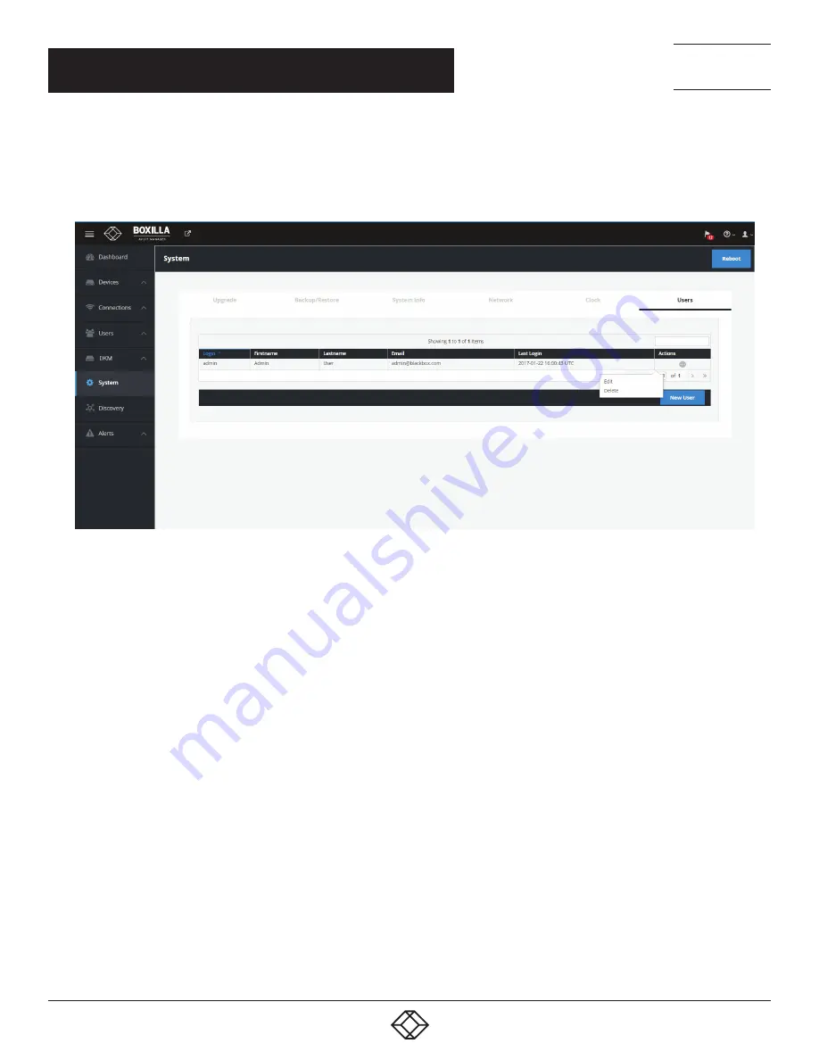
You are strongly recommended to change the default admin password as one of your first actions:

Š

Š

Click on System button on the main menu and then select the Users tab as shown in Figure 15.

Š

Š

Click the “…” icon on the Admin row and click on the edit option.

FIGURE 15. CHANGING ADMIN USER PASSWORD

This allows the Admin user to be edited. The default password would be changed for security. The other properties can be used as 
required.

CHAPTER 5: BOXILLA CONFIGURATION

Summary of Contents for Boxilla

Page 1: ...BXAMGR USER MANUAL 24 7 TECHNICAL SUPPORT AT 1 877 877 2269 OR VISIT BLACKBOX COM BOXILLA AV l IT MANAGER BOXILLA KVM AV IT MANAGER...

Page 2: ...IONS 15 3 1 Video Audio and USB Sharing 15 4 INITIAL INSTALLATION 16 4 1 Hardware Description 16 4 2 LED Identification 17 4 3 Installation Safety 18 4 4 Serial Configuration of IP Address 18 4 5 Brow...

Page 3: ...Devices Statistics 43 8 CONNECTIONS 44 8 1 Connections Manage 44 8 1 1 Connections Add Connection 45 8 1 2 Connections Add Connection Template 48 8 1 3 Connections Delete Connection Template 49 8 2 Co...

Page 4: ...1 11 2 2 How to Upload a License File 92 11 3 System Administration Certificates Upload 93 11 4 System Backup Restore 96 11 5 System System Info 96 11 6 System Settings Thresholds 97 11 7 System Setti...

Page 5: ...XILLA AND EMERALD OR EMERALD OR INVISAPC PROTOCOLS 106 Overview 106 APPENDIX C REGULATORY INFORMATION 107 C 1 FCC and IC Statements 107 C 2 Safety and EMC Approvals and Markings Patent Information 107...

Page 6: ...portant operating and maintenance servicing instructions in the literature accompanying the appliance DANGEROUS VOLTAGE This symbol is intended to alert the user to the presence of uninsulated dangero...

Page 7: ...RT 1 877 877 2269 SYMBOLS USED IN THIS MANUAL POWER OFF This symbol indicates the principal on off switch is in the off position PROTECTIVE GROUNDING TERMINAL This symbol indicates a terminal that mus...

Page 8: ...250 W Dimensions System 1 73 H x 17 3 W x 10 6 D 4 4 x 44 x 26 8 cm Shipping box 7 2 H x 22 4 W x 15 4 D 18 5 x 57 x 39 cm Weight System 10 96 lb 4 98 kg Shipping 14 92 lb 6 78 kg Compatibility Works...

Page 9: ...irtual desktop over a standard TCP IP network Physical PCs Workstations Servers have an Emerald or InvisaPC Transmitter unit physically connected to provide communication over the TCP IP network The p...

Page 10: ...itches The Emerald or InvisaPC family is composed of Receivers Transmitters and Managers Boxilla is the Enterprise class Manager for Emerald or InvisaPC and Modular and Compact DKM KVM Matrix Switches...

Page 11: ...onnections defines how a Receiver can connect to a Transmitter or a Virtual Machine with properties such as private or share mode USB re direction enabled or disabled among others Alerts events detect...

Page 12: ...12 1 877 877 2269 BLACKBOX COM NEED HELP LEAVE THE TECH TO US LIVE 24 7 TECHNICAL SUPPORT 1 877 877 2269 FIGURE 2 BOXILLA DASHBOARD EXAMPLE CHAPTER 2 PRODUCT OVERVIEW...

Page 13: ...each Receiver has a copy of the database This enables each Receiver to continue operation log users in make connections as required even if the Manager goes off line 2 3 BOXILLA SCREEN LAYOUT Boxilla...

Page 14: ...lla we strongly recommend that Static IP addresses are assigned to Emerald or InvisaPC devices or that you use DHCP addresses with infinite time outs 2 4 1 AUTO LOGIN In Auto Login Mode turning on the...

Page 15: ...ial environmental issues using advanced optimized compression to enable visually lossless video over standard low bandwidth networks rather than a proprietary connection or dedicated gigabit networks...

Page 16: ...the Boxilla package have been verified the first task is to configure the IP address of the unit This can be set in two ways 1 using the serial port and 2 using the network port via a browser Serial N...

Page 17: ...USB Type A ports USB 3 0 used for exporting log files Power switch ON OFF switch 3 prong outlet 100 240 VAC 50 60 Hz CONNECT THE POWER 1 Locate the AC line cord 2 Attach the AC line cord to the power...

Page 18: ...is 192 168 1 24 and needs to be configured to an appropriate address for where it will be deployed To access the serial menu connect to the DB9 connector on the front of the unit The serial port has a...

Page 19: ...CREEN NOTE Only the Network port pointed to in Figure 6 on the right hand side one when you look at the Boxilla unit from the front is currently operational The other port is reserved for a future fea...

Page 20: ...losed rack assembly the operating temperature of the rack environment may be greater than room ambient Use care not to exceed the rated maximum ambient temperature of the Boxilla unit Reduced Air Flow...

Page 21: ...21 1 877 877 2269 BLACKBOX COM NEED HELP LEAVE THE TECH TO US LIVE 24 7 TECHNICAL SUPPORT 1 877 877 2269 FIGURE 12 ESD CONNECTION CHAPTER 4 INITIAL INSTALLATION...

Page 22: ...experience always use the latest versions of supported browsers 5 2 LOGIN Ensure the Boxilla unit is powered up Wait two minutes after applying power before attempting to access to allow the system t...

Page 23: ...23 1 877 877 2269 BLACKBOX COM NEED HELP LEAVE THE TECH TO US LIVE 24 7 TECHNICAL SUPPORT 1 877 877 2269 CHAPTER 5 BOXILLA CONFIGURATION FIGURE 14 BOXILLA INITIAL SCREEN ON LOGIN...

Page 24: ...your first actions Click on System button on the main menu and then select the Users tab as shown in Figure 15 Click the icon on the Admin row and click on the edit option FIGURE 15 CHANGING ADMIN US...

Page 25: ...ver 2 Change the default password for the default user admin for security NOTE Make sure that your computer can view the new IP address otherwise the Boxilla server will appear to be offline Depending...

Page 26: ...d or InvisaPC discovery protocol is not enabled i e routers do not have multicast routing enabled the administrator will have to manually add in devices not on its subnet i e add in each device indivi...

Page 27: ...etween the reported state on the Manager and that of the device This may occur where the device was removed from the Manager s database when the device was off line or if the Manager was restored to f...

Page 28: ...en specified an unmanaged device can now be set to be part of this Boxilla s managed domain This is done by clicking on the Manage option shown in Figure 18 This causes the device s state to change fr...

Page 29: ...dress of the device to be added and click on Get Information This causes Boxilla to retrieve the device s information if reachable If Boxilla has no valid path on the network to the device or IP addre...

Page 30: ...powers up automatically when power is applied or needs the power button to be pressed Auto Login whether an Emerald or InvisaPC Receiver will automatically login as a specific user on power up OSD Res...

Page 31: ...atistics These options are described in the following sections Click on Settings and the following screen appears FIGURE 22 DEVICES SETTINGS SCREEN Click on Video Settings in the middle of this screen...

Page 32: ...iting Configuring Configured Failed If you Edit a Template the updated template is applied to all devices that use that Template The workflow for the Status field here is Waiting Configuration Configu...

Page 33: ...n from 0 to 5 seconds EDID Settings DVI 1 Choose from 1920 x 1080 1920 x 1200 1680 x 1050 1280 x 1024 or 1024 x 768 EDID Settings DVI 2 Choose from 1920 x 1080 1920 x 1200 1680 x 1050 1280 x 1024 or 1...

Page 34: ...emplate button at the top of the Devices Settings screen The Delete Appliance Template screen pops up Select the template you want to delete from the drop down menu then click the Delete button to del...

Page 35: ...he System Properties Settings screen with editable options pops up Changes can be saved or canceled FIGURE 27 EDIT SYSTEM PROPERTIES SCREEN Video Quality Select from these options Best Quality 2 Defau...

Page 36: ...eceiver then the Default or Basic options should be used OSD option FIGURE 28 ABSOLUTE MOUSE SCREEN Mouse Keyboard Timeout Choose an option from 0 to 5 seconds EDID Settings DVI 1 Choose from 1920 x 1...

Page 37: ...to cancel the changes without saving FIGURE 29 EDIT INDIVIDUAL DEVICE SETTINGS SCREEN An individual device can have various operations performed on it by clicking on the icon on the row for the devic...

Page 38: ...eck its reachability 7 1 4 APPLY BULK UPDATE SETTINGS To update the individual device settings all at once click on the Bulk Update button in the middle of the Devices Settings screen From the drop do...

Page 39: ...ck the Activate button for the specific version of firmware from the Release options icon For Emerald or InvisaPC this needs to be done for both Receivers DTX R or EMD4K R and Transmitters DTX T or EM...

Page 40: ...UPGRADE SELECTION Once the administrator has selected devices to be upgraded typically all devices that mis match the active firmware version the administrator clicks the Upgrade button on the page to...

Page 41: ...ges to the settings when a user logs in to the device To ensure global settings are changed on all units at the same time the Administrator should log out all Users FIGURE 34 DEVICE SETTINGS CONFIGURA...

Page 42: ...e connected to a source Transmitter without any keyboard or mouse activity Once the session reaches the inactivity timer limit the user will be logged out of the connection and return to the OSD on Em...

Page 43: ...n the user attempts to log in the login will now take the following steps in this order 1 The login credentials are checked to see if the user is configured locally on the Receiver If the user exists...

Page 44: ...e connections are listed shown in Figure 36 FIGURE 36 CONNECTIONS MANAGE SCREEN The table shows the connection name whether the connection is linked to a connection template see section 8 1 2 connecti...

Page 45: ...n row The parameters for a connection are defined in more detail in section 8 1 1 When you left click on a connection name a popup box appears that tells you details about the connection and gives you...

Page 46: ...a unique name for the new connection The name can be between 1 and 32 characters The name can be composed of any Alphanumeric characters and special characters except for IP Address Hostname the IP ad...

Page 47: ...his setting has no effect on a single video head Emerald or InvisaPC USB Redirection When set this enables non keyboard and non mice devices to be redirected for this connection Audio When set this en...

Page 48: ...io and Persistent Connection FIGURE 40 CONNECTION TYPE PRIVATE 8 1 2 CONNECTIONS ADD CONNECTION TEMPLATE Connection Templates are used to aid in the creation of connections Templates define a set of p...

Page 49: ...currently assigned to connections If you wish to delete a template that is associated with a connection you will first need to remove the template from the connection 8 2 CONNECTIONS GROUPS Boxilla 1...

Page 50: ...ORT 1 877 877 2269 CHAPTER 8 CONNECTIONS Once a connection group has been added you will see the following screen FIGURE 44 UPDATED CONNECTION GROUP SCREEN You can manage connections by adding or remo...

Page 51: ...You can add manage groups from individual Users under Users Manage Once a user logs in at the appliance GUI all the assigned connections both individual and group connections with be visible to the us...

Page 52: ...be prompted FIGURE 49 SUCCESS MESSAGE By dissolving a group the group no longer appear under Connections Groups but the active connections are retained with the users logged in Unlike Delete groups D...

Page 53: ...HAPTER 8 CONNECTIONS FIGURE 50 DELETE THE CONNECTION GROUP Confirm with OK and a confirmation message about deletion is displayed FIGURE 51 CONFIRM DELETION The maximum number of connection groups is...

Page 54: ...connections the name of the connection the Receiver in the connection the user who is logged into the Receiver the type of connection e g private or shared the Transmitter in the connection and then s...

Page 55: ...LIVE 24 7 TECHNICAL SUPPORT 1 877 877 2269 CHAPTER 8 CONNECTIONS FIGURE 53 ACTIVE CONNECTIONS 8 4 CONNECTIONS VIEWER On the Connections drop down menu click on Viewer The Emerald or InvisaPC Connecti...

Page 56: ...Connection Viewer page reflect this by displaying the connection name alongside all the attached receivers To detach one of the receivers move your mouse over that receiver tile and you will see an X...

Page 57: ...listed In Emerald or InvisaPC Viewer Preset Manage you can rearrange the preset priority to change what presets display on th main Viewer screen Essentially you can pick your top three presets FIGURE...

Page 58: ...LACKBOX COM NEED HELP LEAVE THE TECH TO US LIVE 24 7 TECHNICAL SUPPORT 1 877 877 2269 CHAPTER 8 CONNECTIONS The icons on the sources screen are FIGURE 59 ICONS ON THE SOURCES SCREEN FIGURE 60 SELECT D...

Page 59: ...Any Tx Vm and RX not selected in this preset type will become inactive when this preset is launched Click Complete to save the preset FIGURE 62 SAVE PRESET SCREEN The following methods are available t...

Page 60: ...gs etc 2 Power User Users of this class can modify resolution for connections to virtual desktops and change his her local password 3 Standard Users Users of this class can only select from a list of...

Page 61: ...ord can be any valid password for a Microsoft O S This means the password cannot contain User Privilege This field defines the type of user the new user will be Administrator General User or Power Use...

Page 62: ...existing users list of connections To remove a connection from a user select the specific connection in the Selected list i e current connections allocated to the user and click on the button Click S...

Page 63: ...VE THE TECH TO US LIVE 24 7 TECHNICAL SUPPORT 1 877 877 2269 CHAPTER 9 USERS FIGURE 66 CONNECTION FAVORITES SCREEN 4 Listing Connection Favorites When a user log in they can view their assigned favori...

Page 64: ...system click on the icon on the row of the user to be deleted and click on the delete option 9 3 USER ACTIVE The User Active page shows a list of all the users logged in to an Emerald or InvisaPC Rec...

Page 65: ...77 877 2269 CHAPTER 9 USERS 9 4 MANAGE GROUPS You can add manage groups from individual Users under Users Manage Once the users are mapped under a group all the connections and users associated to the...

Page 66: ...66 1 877 877 2269 BLACKBOX COM NEED HELP LEAVE THE TECH TO US LIVE 24 7 TECHNICAL SUPPORT 1 877 877 2269 CHAPTER 9 USERS FIGURE 70 USER GROUP ALLOCATION SCREEN...

Page 67: ...llow these steps 1 Create desired InvisaPC Connection 2 Add a DKM Switch under Boxilla DKM Switches 3 Create a Virtual CPU on the DKM JavaTool named the same name as the InvisaPC Connection Physically...

Page 68: ...L SUPPORT 1 877 877 2269 FIGURE 72 CREATE A VIRTUAL CPU OPTION You will then have the option to name your Virtual CPU IMPORTANT This name must be the same as the InvisaPC Connection name that you want...

Page 69: ...er the Assignment tab on the main menu on the left side of the application window Here you can assign your new Virtual CPU to the real CPU that s physically connected into your InvisaPC receiver This...

Page 70: ...HELP LEAVE THE TECH TO US LIVE 24 7 TECHNICAL SUPPORT 1 877 877 2269 Next click Save Online Changes This pushes the changes down to the DKM switch so even if it reboots it will hold onto the new setti...

Page 71: ...SUPPORT 1 877 877 2269 HOW TO ENABLE LAN ECHO Next you must Enable LAN Echo This will enable the switch to echo the results of the connection initiations to the network where Boxilla can put them up a...

Page 72: ...ION 10 3 STEPS TO ADD SWITCHES Under Boxilla to add the DKM switch navigate to DKM Switches and click the Add Switch blue button on the top right of the screen FIGURE 77 ADD SWITCH SCREEN The Add new...

Page 73: ...CAL SUPPORT 1 877 877 2269 Once the switch is added successfully it gets listed with an online status FIGURE 79 ONLINE STATUS OF SWITCH If you wish to revert select Delete from the dropdown list withi...

Page 74: ...A SWITCH Once the switch is added successfully all DKM CONs and DKM CPUs physical connected will be listed on Boxilla Also any Virtual CPUs configured on the DKM switch will be listed Boxilla will aut...

Page 75: ...Boxilla audited the DKM switch Find the Virtual CPU in the Ports list on the DKM Switches page Click the options button on the right hand side to Attach to InvisaPC Connection NOTE It is not possible...

Page 76: ...options 1 Manual connections using Add custom Source which lasts until the connection is broken 2 Saving connection configurations as Presets which can be activated on demand To detach a connection le...

Page 77: ...ADD CUSTOM SOURCE SCREEN Once these connections are listed each connection needs at least one destination added to form a functional connection Connections have the following options 1 Detach Source B...

Page 78: ...D HELP LEAVE THE TECH TO US LIVE 24 7 TECHNICAL SUPPORT 1 877 877 2269 FIGURE 87 MANAGE PRESETS BUTTON Search of available destinations can be completed within the Add Destinations popup box FIGURE 88...

Page 79: ...US LIVE 24 7 TECHNICAL SUPPORT 1 877 877 2269 CHAPTER 10 DKM INTEGRATION FIGURE 89 ADD DESTINATION POPUP BOX ACTIVATE SELECTED BUTTON Select the Destinations from the available destinations and click...

Page 80: ...SUPPORT 1 877 877 2269 CHAPTER 10 DKM INTEGRATION Once Activated connections get listed under the Viewer screen FIGURE 91 VIEWER SCREEN Active connections are listed under the Connections link Each c...

Page 81: ...877 877 2269 CHAPTER 10 DKM INTEGRATION 10 5 PRESETS Under Viewer click Manage Presets then click Create Custom and select one or more available sources FIGURE 93 CREATE CUSTOM PRESETS Next select one...

Page 82: ...type The full type is applied to all the CONS and CPUS Any CONs and CPUs not selected in this preset type will become inactive when this preset is launched Click Complete to save the preset FIGURE 95...

Page 83: ...TED SCREEN Connections started via Presets will be displayed in the work area with the following options 1 Detach Source Break the connection by detaching the source 2 Detach Destination Break the con...

Page 84: ...onnect a connection while active status click on x on either destination source in case of one to one only FIGURE 98 DESELECT A SOURCE DESTINATION 10 6 ATTACHING VIRTUAL CPUS TO INVISAPC RX Virtual CP...

Page 85: ...HAPTER 11 SYSTEM The System button in the main menu brings up the System Administration Upgrade screen shown next This screen allows the Boxilla unit itself to be managed upgrade the firmware FIGURE 1...

Page 86: ...877 2269 CHAPTER 11 SYSTEM generate your own self signed certificate backup restore the database go to System Adminstration Backup Restore FIGURE 102 BACKUP RESTORE DATABASE SCREEN check system infor...

Page 87: ...24 7 TECHNICAL SUPPORT 1 877 877 2269 CHAPTER 11 SYSTEM set thresholds for alerts go to System Settings Thresholds page FIGURE 104 SET THRESHOLDS FOR ACTIVE ALERTS SCREEN change network settings go t...

Page 88: ...VE 24 7 TECHNICAL SUPPORT 1 877 877 2269 CHAPTER 11 SYSTEM set system time or Clock go to System Settings Clock page FIGURE 106 SYSTEM CLOCK SCREEN create edit Boxilla users go to System Administratio...

Page 89: ...VE THE TECH TO US LIVE 24 7 TECHNICAL SUPPORT 1 877 877 2269 CHAPTER 11 SYSTEM The administrator can reboot the Boxilla unit by clicking on the Reboot button on the top right of the System Administrat...

Page 90: ...NT Ensure the Boxilla unit stays powered up during the upgrade Losing power during an upgrade may cause the unit to cease functioning 11 2 SYSTEM LICENSE PAGE BOXILLA LICENSING Boxilla licensing allow...

Page 91: ...EQUEST A LICENSE To procure a new license file generate the info file from your current system using Generate Info File option within License link The info file will be downloaded onto the local machi...

Page 92: ...OX COM NEED HELP LEAVE THE TECH TO US LIVE 24 7 TECHNICAL SUPPORT 1 877 877 2269 CHAPTER 11 SYSTEM 11 2 2 HOW TO UPLOAD A LICENSE FILE Once you receive the license file upload the new license FIGURE 1...

Page 93: ...enerated form a registered Certificate Authority CA The new system allows the users to upload these files into Boxilla so they can upload the other key into their browser This will then act as an auth...

Page 94: ...ED HELP LEAVE THE TECH TO US LIVE 24 7 TECHNICAL SUPPORT 1 877 877 2269 CHAPTER 11 SYSTEM FIGURE 113 UPLOAD CERTIFICATE BUTTON FIGURE 114 SELECT THE CERTIFICATE FILE A green alert on the page indicate...

Page 95: ...CAL SUPPORT 1 877 877 2269 CHAPTER 11 SYSTEM FIGURE 115 GREEN ALERT To delete any existing certificates click on the delete cert button under certificates tab FIGURE 116 DELETE BUTTON A popup message...

Page 96: ...to the Backup Table Once the upload has been completed the administrator clicks on Import on the icon options on the row on the Backup table to be used to restore the Boxilla unit settings Clicking on...

Page 97: ...119 ALERT THRESHOLDS The Warning Threshold sets the level above which a measurement must be below to be classified as normal or at info level Measurements above the Warning Threshold and below Critica...

Page 98: ...the IP settings for the Boxilla unit and enables the Administrator to change the IP settings for the Boxilla unit enter IP address Net Mask and Gateway in IPv4 format and click Apply FIGURE 120 SYSTEM...

Page 99: ...e System Administration Boxilla Users tab shows a table of users for the Boxilla unit not the same as users for the managed domain as shown below System Users FIGURE 122 SYSTEM USERS FIGURE 123 NEW SY...

Page 100: ...Warning Alert Events that indicate a potential serious negative impact on the system is classified as a Critical event Events that are classified as Critical are Failure to update the IP Address of a...

Page 101: ...just Critical Warning or Info by selecting the appropriate tab on the Alerts History screen as shown in Figure 124 FIGURE 124 ALERTS HISTORY 12 2 ALERTS ACTIVE Active Alerts are alerts that are curre...

Page 102: ...are counted on each Receiver when a user fails a login attempt Unauthorized Connections are counted on Receivers and Transmitters when they detected something has attempted to connect to them in an un...

Page 103: ...e Receiver on the active connection Transmitter the name of the Transmitter on the active connection FPS the current frames per second being encoded transferred on the connection The contents of the l...

Page 104: ...n the filter box contents The table portion has the following columns Receiver the receiver name that has been logged into Username the user name that has logged into the Receiver User Type the type o...

Page 105: ...nd power up 2 Before connecting the new Boxilla unit to the main network connect the Boxilla unit to a network switch that is isolated from the main network 3 Use a computer connected to the same swit...

Page 106: ...is located to be discovered Emerald or InvisaPC devices respond to the discovery multicast by sending a UDP unicast back to the Manager IP address on the same port Port 39150 Once an Emerald or Invisa...

Page 107: ...compliance could void the user s authority to operate the equipment This digital apparatus does not exceed the Class A limits for radio noise emission from digital apparatus set out in the Radio Inte...

Page 108: ...e consequential or cost of cover damages resulting from any errors in the product information or specifications set forth in this document and Black Box Corporation may revise this document at any tim...

Page 109: ..._______________________________________________________ __________________________________________________________________________________________________ _____________________________________________...

Page 110: ..._______________________________________________________ __________________________________________________________________________________________________ _____________________________________________...

Page 111: ...______ __________________________________________________________________________________________________ ______________________________________________________________________________________________...

Page 112: ...NEED HELP LEAVE THE TECH TO US LIVE 24 7 TECHNICAL SUPPORT 1 877 877 2269 COPYRIGHT 2018 BLACK BOX CORPORATION ALL RIGHTS RESERVED BXAMGR_USER_REV2 1 PDF...

Reviews: