background image

DVI-D CATX/FIBER KVM-EXTENDER 

24 


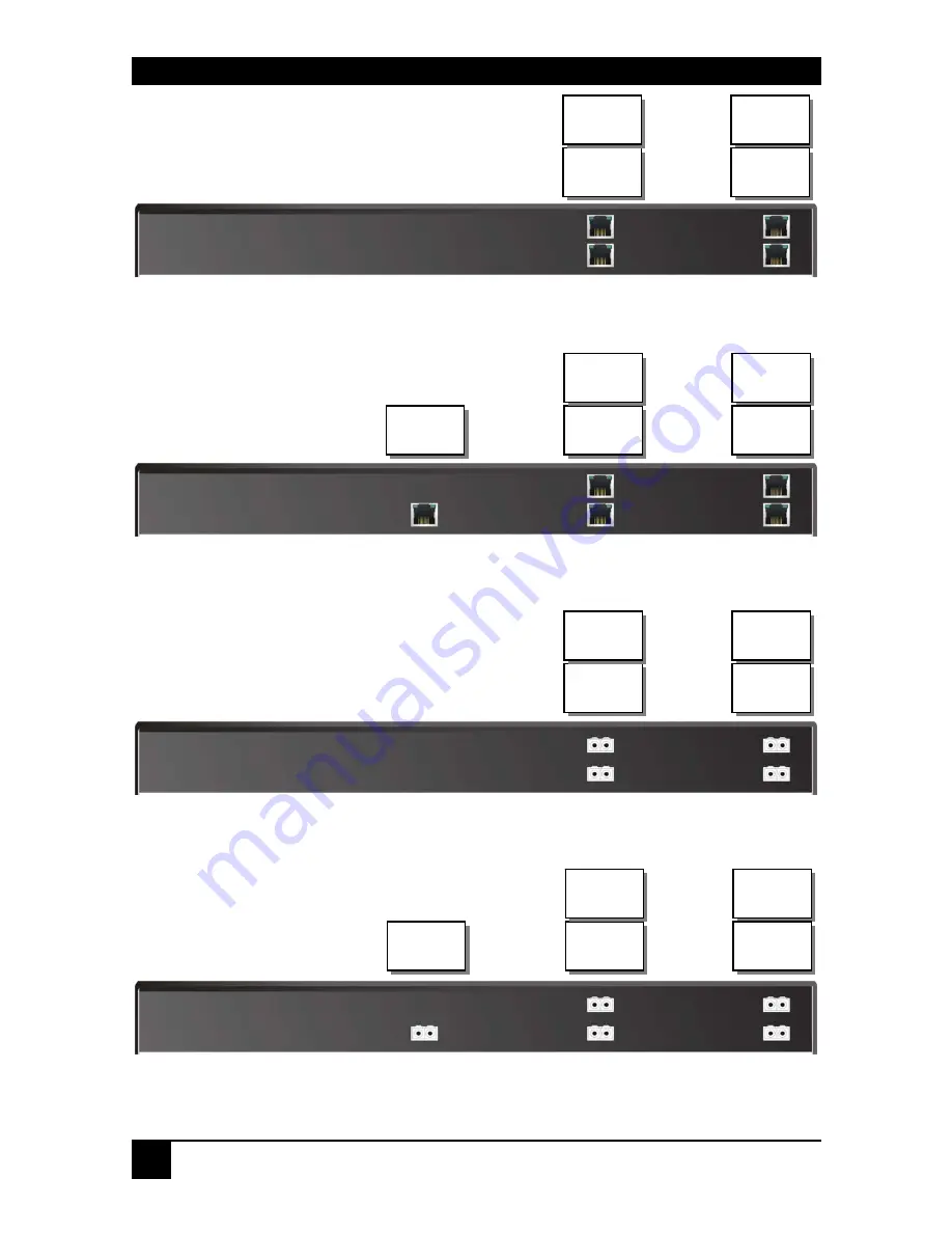
DVI-D KVM-Extender Type ACS4422A-R2 Local/Remote Unit 


DVI-D KVM-Extender Type ACS4442A-R2 Local/Remote Unit 


DVI-D KVM-Extender Type ACS4422A-R2-xx Local/Remote Unit 


DVI-D KVM-Extender Type ACS4442A-R2-xx Local/Remote Unit 

Port 2

DVI 2 

Port 1

DVI 1 

Port 3

DVI 3 

Port 4

DVI 4 

Port 2

DVI 2 

Port 1

DVI 1 

Port 3

DVI 3 

Port 4

DVI 4 

Port 5

USB 2.0 

Port 2

DVI 2 

Port 1

DVI 1 

Port 3

DVI 3 

Port 4

DVI 4 

Port 2

DVI 2 

Port 1

DVI 1 

Port 3

DVI 3 

Port 4

DVI 4 

Port 5

USB 2.0 

Summary of Contents for ACS4422A-R2

Page 1: ...ACS4422A R2 ACS4422A R2 MM ACS4422A R2 SM ACS4442A R2 ACS4442A R2 MM ACS4442A R2 SM ACS4481A R2 SM ACS4482A R2 SM DVI D CATx Fiber KVM Extender Quad Head Manual http www blackbox com ...

Page 2: ... Extender is the best way to solve all problems in remotely locating your console 2 families with 4 different types are available Quad Head devices for USB HID or USB 2 0 transparent CATx Multimode Singlemode and CWDM This manual will tell you all about your new DVI D CATx Fiber KVM Extender including how to install operate and troubleshoot it For an introduction to the Extender see Chapter 2 The ...

Page 3: ...es the manufacturer assume any liability for damages resulting from the use of the information contained herein The manufacturer reserves the right to change the specifications functions or circuitry of the product without notice The manufacturer cannot accept liability for damage due to misuse of the product or due to any other circumstances outside the manufacturer s control whether environmenta...

Page 4: ...DVI D CATX FIBER KVM EXTENDER 4 ...

Page 5: ...able protection against harmful interference when the equipment is operated in a commercial environment This equipment generates uses and can radiate radio frequency energy and if not installed and used in accordance with the instruction manual may cause harmful interference to radio communications Operation of this equipment in a residential area is likely to cause harmful interference in which c...

Page 6: ...ot place a power supply directly on top of a unit Do not obstruct a unit s ventilation existing holes To safeguard against personal injury and avoid possible damage to equipment or property please observe the following Only use power supplies originally supplied with the product or manufacturer approved replacements Do not attempt to dismantle or repair any power supply Do not use a power supply i...

Page 7: ...ge Contents 15 3 2 Interconnection Cable Requirements 17 3 3 System Setup 19 3 4 Diagnostic LEDs 25 4 Service Setup 27 4 1 Setup at the Local Unit 27 4 2 Setup at the Remote Unit 30 5 Troubleshooting 31 Appendix A Example Applications 35 Appendix B Rack Mount Options 37 Appendix C Audio Serial Support 38 Appendix D Calling Technical Support 39 Appendix E Specifications 41 Appendix F Connectors 43 ...

Page 8: ...his manual Install system 1 Connect Remote unit to KVM 2 Connect Local unit to CPU or switch 3 Connect Local and Remote units with matching interconnection cable CATx or Fiber 4 Power up the system Done YES NO Link LED illuminated NO NO YES Check p s u s and connection to power outlet Power LED illuminated Check the CATx or Fiber cable and its connectors Check settings of graphic card or boot CPU ...

Page 9: ...ts offer dual access allowing the connection of a second monitor close to the computer 2 2 Glossary The following terms are used in this guide CATx Any Category 5 5e 6 or higher cable solid wires type AWG24 Although flexible AWG27 7 cables can be used too the lengths of flexible cables count twice in the calculation of the total distance Fiber 9µ Singlemode or 50µ 62 5µ Multimode fiber cable KVM K...

Page 10: ...I D CATX FIBER KVM EXTENDER 10 DVI D CATx KVM Extender system example CPU with DVI D Quad Head Graphic card DVI D CATx KVM Extender system Local Console Remote Console Optional additional USB 2 0 devices ...

Page 11: ...s no guarantee for this The DVI D CATx Fiber KVM Extender for USB HID is NOT suitable for use with other USB devices like Scanner webcams data sticks etc The USB HID device never supports more than two devices Keyboard and Mouse or Keyboard and Touch screen etc but not e g Keyboard Mouse and Touch screen simultaneously A hub is allowed but does not raise the number of supported devices Optionally ...

Page 12: ...imode ACS4422A R2 SM KVM Extender Quad Head DVI D USB HID Singlemode ACS4442A R2 KVM Extender Quad Head DVI D USB 2 0 CATx ACS4442A R2 MM KVM Extender Quad Head DVI D USB 2 0 Multimode ACS4442A R2 SM KVM Extender Quad Head DVI D USB 2 0 Singlemode ACS4481A R2 SM KVM Extender Quad Head DVI D USB HID Singlemode CWDM ACS4482A R2 SM KVM Extender Quad Head DVI D USB 2 0 Singlemode CWDM Upgrade Kits ACS...

Page 13: ...screens graphics tablets barcode readers or similar are supported but there is no guarantee for this The USB HID is NOT suitable for use with other USB devices like Scanner webcams data sticks etc Devices with USB HID support ONLY Keyboard and Mouse It s possible that other HID devices Human Interface Device like touch screens graphics tablets barcode readers or similar are supported but there is ...

Page 14: ...g the moment of switching to the next frame The transmission of screen data is not synchronous to the screen change of the graphic card Normally the transmission is terminated during displaying a frame on the screen If the device switches to the new frame during the displaying period of the old frame somewhere on the screen it s possible and that you can see horizontal screen breaks in the moment ...

Page 15: ...ng items in your extender package all types DVI D CATx Fiber KVM Extender pair Local Unit Remote Unit 2x US type power cords and power supplies User manual Quick Setup 1x KVM CPU cable set 1 8m with one side PS 2 6 pin mini DIN male keyboard and mouse connector and DVI D video DVI D dual link male connector other side DVI D video DVI D dual link male connector 1x PS2 Keyboard Mouse adapter to conn...

Page 16: ...8m with one side DSUB9pin female connector 2x 3 5mm stereo plugs other side miniDIN8pin male connector ACS4442A R2 ACS4442A R2 MM ACS4442A R2 SM and ACS4482A R2 SM additionally 1x USB 1 8m cable USB type A to type B If anything is missing please contact Technical Support see Appendix D Calling Technical Support ...

Page 17: ...he maximum distance is reduced to approx half the value of solid cables A point to point connection is required Having one or more patch panels in the line is possible and allowed Not allowed is a connection from the CATx link interface RJ45 to any other products especially telecommunications or network equipment Fiber Cable Two strands of fiber are required for Single Head devices eight strands f...

Page 18: ...ce on Multimode fibers to twice the regular length Anyway this cannot be guaranteed and must be evaluated by the end user at own expense Power Supply Connect the AC outlet jack to the Plug terminal on the front of both Local and Remote units ...

Page 19: ... and PS2 Keyboard connector The PS2 Keyboard connector is purple and the PS2 Mouse connector is green 4 Connect the interconnect cable to the INTERCONNECT socket s 5 Connect the AC power supply to power the unit 6 For a dual access system connect the monitors for the Local console to the appropriate ports on the Local unit The ports may also be used to feed into a KVM switch To the local PS2 Keybo...

Page 20: ...rough equipped adapter remote DVI Monitor port connect to Remote console monitor 1 2 Remote PS2 mouse port Connect to AC Power supply 100 230VAC 50 60Hz local DVI Monitor port Connect to Local console monitor 1 2 Connect to CPU DVI 3 keyboard mouse PS2 Connect to CPU serial audio ports Connect to CPU USB Connect to AC Power supply 100 230VAC 50 60Hz Remote PS2 keyboard port Remote USB HID ports Co...

Page 21: ... DVI Monitor port connect to Remote console monitor 1 2 Remote PS2 mouse port Connect to AC Power supply 100 230VAC 50 60Hz local DVI Monitor port Connect to Local console monitor 1 2 Connect to CPU DVI 3 keyboard mouse PS2 Connect to CPU serial audio ports Connect to CPU USB Connect to AC Power supply 100 230VAC 50 60Hz Remote PS2 keyboard port Remote USB HID ports Connect to CPU serial interface...

Page 22: ... Connect to CPU USB Connect to AC Power supply 100 230VAC 50 60Hz Remote PS2 keyboard port Remote USB HID ports Connect to CPU serial interface Connect to CPU Audio OUT Audio IN remote DVI Monitor port connect to Remote console monitor 3 4 Connect to CPU DVI1 2 4 local DVI Monitor port Connect to Local console monitor 3 4 Local keyboard mouse port Solely Keyboard may be plugged in directly keyboar...

Page 23: ...mote PS2 mouse port Connect to AC Power supply 100 230VAC 50 60Hz local DVI Monitor port Connect to Local console monitor 1 2 Connect to CPU DVI 3 keyboard mouse PS2 Connect to CPU serial audio ports Connect to CPU USB Connect to AC Power supply 100 230VAC 50 60Hz Remote PS2 keyboard port Remote USB HID ports Connect to CPU serial interface Connect to CPU Audio OUT Audio IN remote DVI Monitor port...

Page 24: ...D KVM Extender Type ACS4422A R2 xx Local Remote Unit DVI D KVM Extender Type ACS4442A R2 xx Local Remote Unit Port 2 DVI 2 Port 1 DVI 1 Port 3 DVI 3 Port 4 DVI 4 Port 2 DVI 2 Port 1 DVI 1 Port 3 DVI 3 Port 4 DVI 4 Port 5 USB 2 0 Port 2 DVI 2 Port 1 DVI 1 Port 3 DVI 3 Port 4 DVI 4 Port 2 DVI 2 Port 1 DVI 1 Port 3 DVI 3 Port 4 DVI 4 Port 5 USB 2 0 ...

Page 25: ...th indicator LEDs Power Video OK Data Error Link Status The Power LEDs are built into the Power switch The location of the LEDs is shown below Diagnostic LEDs at DVI D CATx Extender Diagnostic LED Power Diagnostic LED Video OK Diagnostic LED Data Error Diagnostic LED Link Status ...

Page 26: ...eady Video Okay Green LED Off On No or invalid video signal detected Device ready Link Status Green LED blinking On No CATx connection Device ready Data Error Green LED Off blinking On Device ready Errors through data transmission over CATx Cable Cable too long too high attenuation or too much EMI interferences ...

Page 27: ... Unit Unscrew the Philips type screws at both sides at the bottom of the device Carefully displace the lower and upper shells of the case 4 1 Setup at the Local Unit After unscrewing and opening the upper shell please place the device in this orientation with the CATx connectors to the right and the electrical connectors to the left The main PCBs then will look like this Use the diagram to locate ...

Page 28: ...internal DDC Table To load the DDC Information from the Remote Monitor s into the internal DDC Table please precede the following steps Power up the CPU the Local Unit the Remote cables to the CPU connected and the Monitor Pull the Monitor Cable s from the Remote Unit Quad Head devices All Monitors Switch ON the Monitor s if switched OFF ALL Monitors Plug the Video Cable of the Remote Monitor s in...

Page 29: ...itted When the video data do not allow reducing data enough the colors are automatically reduced to 16Bit This is auto selected in each line of the screen picture at any time This mode makes the best compromise between speed and color depth Please select 24Bit if you want to have under all circumstances highest colours but perhaps with reduced frame rates Color depth JP3 16Bit 24Bit AUTOSELECT col...

Page 30: ...Normally the transmission is terminated during displaying a frame on the screen If the device switches to the new frame during the displaying period of the old frame somewhere on the screen it s possible that you can see horizontal screen breaks in the moment of switching On the other hand the device must idle until the actual frame is displayed completely until VSYNC the number of frames per seco...

Page 31: ...a have to be reduced before transmitting This is done in a first step by a so called RLE Run Length Encoding algorithm If this loss less compression does not reach the required amount frames are dropped The frame actually transmitted is transmitted completely even if the graphic card generates a new frame This new frame is discarded Because of this behaviour the count of frames per second fps may ...

Page 32: ...s connected to the PC keyboard port to provide power You have plugged keyboard and mouse cable to the CPU ports while the CPU was powered There you first have plugged the Keyboard cable then the Mouse cable Please unplug and re plug the keyboard cable If the mouse still does not work please reboot the CPU The K M sub electronics are powered by the CPU keyboard port If you first plug in the keyboar...

Page 33: ...c Depending to our experiences even a step from 100msec delay to 140msec i e by inserting an extender system to a CPU monitor link may cause visible effects Please note that even a monitor directly connected to a CPU has a delay of 70 to 175msec So under special conditions even the bare CPU monitor link shows this rubber band behaviour If you now insert an extender system the problem may occur and...

Page 34: ...DVI D CATX FIBER KVM EXTENDER 34 Other USB devices Your USB device does not work You have connected a non HID device There are supported HID devices only All other devices are dismissed ...

Page 35: ...5 Appendix A Example Applications This section illustrates some specific applications using the DVI D CATx Extenders DVI D CATx KVM Extender with optional secondary screen set DVI D CATx KVM Extender with optional secondary screen set ...

Page 36: ...KVM EXTENDER 36 A Quad Head CPU is remotely located The USB 2 0 access provides the power of a complete workspace including printer scanner memory stick CD ROM DVI D CATx KVM Extender with full USB 2 0 high speed access ...

Page 37: ...ice local or remote unit can be mounted into a 19 Server Rack Mounting instruction Align the holes on the base plate with the vacant screw holes on the base of the device Fasten the base of the unit to the plate of the mounting kit Only use the supplied short screws to prevent damages on the PCB s Blanking plates are not used for this application base plate 8 pieces spacer M2 5x2 8 pieces M2 5x5 P...

Page 38: ...of powered speakers at the other end of the link Stereo audio may be transmitted either way across the link simultaneously No set up is required unless a microphone is connected to the remote unit Connect up the extender as follows Take the line level output from your sound card green connector and connect to Line In on the extender A set of powered speakers may be connected directly to Line Out a...

Page 39: ...urs The components involved in the problem that is what type of computers what type of keyboard brand of mouse make and model of monitor type and make of cable etc Any particular application that when used appears to create the problem or make it worse The results of any testing you ve already done To solve some problems it might be necessary to upgrade the Extender s firmware If this turns out to...

Page 40: ...ackbox fr 33 820 07 09 11 33 820 05 07 09 Germany www black box de techsupp black box de 49 811 5541 110 49 811 5541 499 Ireland www blackbox co uk techhelp blackbox co uk 353 1 662 2466 353 1 662 2477 Italy www blackbox it supporto tecnico blackbox it 39 02 27 404 700 39 02 27 400 219 Netherlands www blackbox nl techsupport blackbox nl 31 30 241 7799 31 30 241 4746 Norway www blackboxnorge no sup...

Page 41: ... RJ45 1000 MBit high speed transmission Wiring according to EIA TIA 568B Gigabit Ethernet Audio Interface Description Bi directional stereo audio link Transmission Method Digitized virtually CD quality audio 16 bit 38 4KHz Signal Levels Line Level 5 Volts Pk Pk maximum Input Impedance 47K Local Unit Connectors 2 x 3 5mm stereo jack socket Line In Line Out Remote Unit Connectors 2 x 3 5mm stereo ja...

Page 42: ...tal STP 17 03170 Four pairs AWG 26 7 wiring acc EIA TIA 568A 1000BaseT Maximum Length of Fibre Cable LC Connector Singlemode 9μm 10 000m 32 750ft Multimode 50μm 400m 1 300ft Multimode 62 5μm 200m 650ft Size and Shipping Weight ACS4422 ACS4442 CATx Multi Singlemode Shipping box 420 x 143 x 43mm 19 x5 6 x1U 2 devices Weight 1 5 kg 3 3lb each 470x250x115mm 18 5 x9 8 x4 5 Weight 3 3kg ACS4481 ACS4482 ...

Page 43: ... data 1 17 T M D S data 0 2 T M D S data 2 10 T M D S data 1 18 T M D S data 0 3 T M D S data 2 GND 11 T M D S data 1 GND 19 T M D S data 0 GND 4 n c 12 n c 20 n c 5 n c 13 n c 21 n c 6 DDC Input SCL 14 5V high impedance 22 T M D S clock GND 7 DDC Output SDA 15 GND 23 T M D S clock 8 Internal use 16 Hot Plug recognition 24 T M D S clock C1 Internal use C3 Internal use C2 n c C5 GND C4 Internal use...

Page 44: ... M D S data 0 3 T M D S data 2 GND 11 T M D S data 1 GND 19 T M D S data 0 GND 4 PS2 KBD CLK 12 PS2 MOUSE CLK 20 PS2 MOUSE VCC IN 5V not required 5 PS2 KBD DATA 13 PS MOUSE DATA 21 PS2 KBD VCC IN 5V always required 6 DDC Input SCL 14 5V In for DDC 22 T M D S clock GND 7 DDC Output SDA 15 GND 23 T M D S clock 8 Analog VSYNC 16 Hot Plug recognition 24 T M D S clock C1 n c C3 n c C2 n c C5 GND C4 n c...

Page 45: ... connector Local Unit Pin 1 KBD DATA 2 MOUSE DATA 3 KBD MOUSE GND 4 VCC 5V 5 KBD CLK 6 MOUSE CLK Keyboard Mouse connector output connector Remote Unit Pin Keyboard Pin Mouse 1 KBD DATA 1 MOUSE DATA 2 2 3 KBD GND 3 MOUSE GND 4 VCC 5V 4 VCC 5V 5 KBD CLK 5 MOUSE CLK 6 6 ...

Page 46: ...DER 46 USB Connector USB Typ B connector at Local Unit Pin Signal 1 VCC 5V Red 2 Data White 3 Data Green 4 GND Black USB Connector USB Typ A connector at Remote Unit Pin Signal 1 VCC 5V Red 2 Data White 3 Data Green 4 GND Black ...

Page 47: ...D DATA 2 2 MOUSE DATA 2 1 MOUSE DATA 3 KBD GND 3 KBD GND 3 MOUSE GND 4 VCC 5V 4 VCC 5V 4 VCC 5V 5 KBD CLK 5 KBD CLK 6 6 MOUSE CLK 6 5 MOUSE CLK Audio serial Adapter to connect audio RS232 to Local Unit Pin 1 AUDIO GND 2 RS232 GND 3 AUDIO OUT RIGHT CHANEL 4 AUDIO OUT LEFT CHANEL 5 RS232 RxD 6 AUDIO IN RIGHT CHANEL 7 AUDIO IN LEFT CHANEL 8 RS232 TxD ...

Page 48: ...Remote Unit only 9 pin DSUB male Remote Unit Pin Signal 1 Not connected 2 RxD 3 TxD 4 DTR 5 GND 6 DSR 7 RTS 8 CTS 9 Not connected CATx Interface Pin out according to EIA TIA 568A 1000BaseT Pin Pin 1 D1 5 D3 2 D1 6 D2 3 D2 7 D4 4 D3 8 D4 1 8 ...

Page 49: ...NOTES ...

Reviews: