background image

AC1037A | AC1037A-XMIT | AC1037A-REC

1

Optical Cable:

The AC1037A operates with most single mode (SM) optical fibers. However, be aware 
that the type of fiber you use will affect the system’s loss budget and the maximum 

transmission distance that it can support.

Troubleshooting:

Multimode fiber optic cable contains an optical fiber with a light carrying “core” that is 
only .0025 inches (62.5 microns) in diameter. Single mode fiber optic cable has an even 
smaller “core,” only .00032 to .0004 inches (8-10 microns). This is smaller than a human 

hair! 

Therefore, any minute particles of dirt or dust can easily block the fiber from accepting 

or radiating light. To prevent this from happening, always use the provided dust caps 
whenever optical connectors are exposed to air. It is also a good idea to gently clean the 

tip of an optical connector with a lint-free cloth moistened with alcohol whenever dust is 

suspected.

The status of the VIDEO and AUDIO indicator LEDs should provide the first clue as to the 
origin of an operational failure. If these are off, it usually means that the fiber is broken or 

has too much attenuation. Next, be certain that the input and output signal connections are 
correct.

If, after reviewing the above possibilities, the system is still not operating, please contact 
the Customer Service Department for further assistance.

Maintenance:

The only maintenance of the AC1037A system that can be provided by the user is to 
ascertain that the optical connectors are free of dust or dirt that could interfere with light 
transmission and that electrical connections are secure and accurate. DANGER! Always 

disconnect the transmitter power before removing the optical fiber from the unit! For as-

sistance with all other repairs, please contact Black Box technical support.

OPERATING POINTERS & TROUBLESHOOTING

Summary of Contents for AC1037A

Page 1: ... SUPPORT INFORMATION Order toll free in the U S Call 877 877 BBOX outside U S call 724 746 5500 FREE technical support 24 hours a day 7 days a week Call 724 746 5500 or fax 724 746 0746 Mailing address Black Box Corporation 1000 Park Drive Lawrence PA 15055 1018 Web site www blackbox com E mail info blackbox com ...

Page 2: ......

Page 3: ...rules which are designed to provide reasonable protection against such interference when the equipment is operated in a commercial environment Operation of this equipment in a residential area is likely to cause interference in which case the user at his own expense will be required to take whatever measures may be necessary to correct the interference Changes or modifications not expressly approv...

Page 4: ...cante 7 El aparato eléctrico debe ser montado a la pared o al techo sólo como sea recomendado por el fabricante 8 Servicio El usuario no debe intentar dar servicio al equipo eléctrico más allá a lo descrito en las instrucciones de operación Todo otro servicio deberá ser referido a personal de servicio calificado 9 El aparato eléctrico debe ser situado de tal manera que su posición no interfiera su...

Page 5: ... de las lineas de energia 16 El cable de corriente deberá ser desconectado del cuando el equipo no sea usado por un largo periodo de tiempo 17 Cuidado debe ser tomado de tal manera que objectos liquidos no sean derramados sobre la cubierta u orificios de ventilación 18 Servicio por personal calificado deberá ser provisto cuando A El cable de poder o el contacto ha sido dañado u B Objectos han caíd...

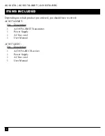
Page 6: ...nding on which product you ordered you should have received AC1037A XMIT Qty Description 1 AC1037A XMIT Transmitter 1 Power Supply 1 AC line cord 1 User Manual AC1037A REC Qty Description 1 AC1037A REC Receiver 1 Power Supply 1 AC line cord 1 User Manual ...

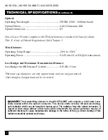
Page 7: ... audio signals TECHNICAL SPECIFICATIONS Video Number of Video Channels 1 single link DVI up to 1920x1200 Video Processing 24 bits no compression or scaling DVI Input Loop through Yes EDID DDC Support Yes from loop through or internal Pixel Clock Range 25 165 Mhz continuous Scanning System Supported Progressive or Interlaced Format Supported RGB or YPrPb Audio Number of Audio Channels 2 unbalanced ...

Page 8: ...udget in dB Distance in km 0 15 dB 15 km Distance specifications are only approximate and are not guaranteed Operating loss budget must not be exceeded DANGER The transmitting element in the AC1037A XMIT unit contains a solid state Laser Diode located within the optical connector This device emits invisible infrared electromag netic radiation which can be harmful to human eyes The radiation from t...

Page 9: ...he loop thru default settings are desired ensure that the Loop Internal EDID Switch is in the Internal position No monitor connection to the transmitter box is required for this loop thru position 4 Connect the video output s on the receiver unit to the DVI D connector s 5 Connect the fiber optic cable between the two AC1037A units 6 Connect the audio input signals to the transmitter stereo jack a...

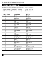
Page 10: ...ter Receiver 1 Red Red 2 Red Red 3 Red Shield Red Shield 4 N C N C 5 N C N C 6 DDC CLK DDC CLK 7 DDC Data DDC Data 8 N C N C 9 Green Green 10 Green Greeen 11 Green Shield Green Shield 12 N C N C 13 N C N C 14 5V Power 5V Power 15 GND for 5V GND for 5V 16 Hot Plug Detect Hot Plug Detect 17 Blue Blue 18 Blue Blue 19 Blue Shield Blue Shield 20 N C N C 21 N C N C 22 Pixel Click Shield Pixel Click Shie...

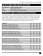
Page 11: ...W Wide EQ Short Cable 10 ft Off Off Off Off BW Medium EQ Short Cable 10 ft On Off Off Off BW Narrow EQ Short Cable 10 ft Off On Off Off BW Very Narrow EQ Short Cable 10 ft On On Off Off BW Wide EQ Medium Cable 10 20 ft Off Off On Off BW Medium EQ Medium Cable 10 20 ft On Off On Off BW Narrow EQ Medium Cable 10 20 ft Off On On Off BW Very Narrow EQ Medium Cable 10 20 ft On On On Off BW Wide EQ Long...

Page 12: ...ideo detected on the input Audio OFF Indicates no audio detected on the transmitter unit BLINKING GREEN Audio detected on the transmitter unit RECEIVER Video OFF Indicates no video detected over the fiber and as a result no video present on the output STEADY GREEN Indicates DVI Video detected over fiber and as a result video present on the output Audio OFF Indicates no audio detected over fiber an...

Page 13: ... of an optical connector with a lint free cloth moistened with alcohol whenever dust is suspected The status of the VIDEO and AUDIO indicator LEDs should provide the first clue as to the origin of an operational failure If these are off it usually means that the fiber is broken or has too much attenuation Next be certain that the input and output signal connections are correct If after reviewing t...

Page 14: ...AC1037A AC1037A XMIT AC1037A REC 14 Notes ...

Page 15: ......

Page 16: ...P N 126650 Copyright 2007 Black Box Corporation All rights reserved 1000 Park Drive Lawrence PA 15055 1018 724 746 5500 Fax 724 746 0746 ...

Reviews: