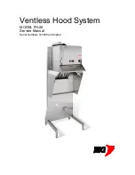
Ventless Hood System
Installation
9
Securing
Wall Mount
After the hood has been located and leveled, secure to building by utilizing the .437 diameter holes
provided in the rear of the fire extinguisher cylinder shelf (Refer to figure below). Using 1/4” lag screw(s),
spacer(s) (if required), and anchor(s) (if required) secure the hood to a wall to prevent movement. The
outside holes are spaced at 16 inches in the event wall studs can position the unit.
Brace Mount
If the unit is being mounted far away from a wall, a brace (angle) secured to the floor may be bolted to the
shelf. This brace must be sufficient to prevent movement of the hood. Seal brace connection to floor
using a food grade RTV. This will prevent grease or food particles from getting beneath the brace.
Summary of Contents for Ventless Hood System FH-28
Page 1: ...Ventless Hood System MODEL FH 28 Service Manual Serial Numbers 123046 and higher ...
Page 20: ...Ventless Hood System Replacement Parts 18 Figure 1 Electrical Box Assembly ...
Page 22: ...Ventless Hood System Replacement Parts 20 Figure 2 Blower Motor Assembly ...
Page 24: ...Ventless Hood System Replacement Parts 22 Figure 3 Right Side Cabinet Assembly ...
Page 29: ...Ventless Hood System Wiring Diagrams 27 Wiring Diagrams ...
Page 30: ...Ventless Hood System Notes 28 Notes ...
Page 31: ...Ventless Hood System Notes 29 ...


