


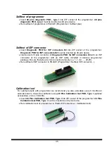


Description of ISP connector
1
2
3
4
5
6
7
8
9
10
11
12
13
14
15
16
17
18
19
20
Front view at ISP connector.
Specification of ISP connector pins depends on the device, which you want to program. You
can find it in the control SW for programmer (Pg4uw), menu
Device / Device Info (Ctrl+F1)
.
Be aware, the ISP programming way of respective device must be selected. It is indicated by
(ISP) suffix after name of selected device.
These specifications correspond with application notes published of device manufacturers.
Used application notes you may find on
section
Support /
Application Notes
.
Note: Pin no. 1 is signed by triangle scratch on ISP cable connectors
.
859 ISP cable
Warnings:
•
Use only attached ISP cable. When you use other ISP cable (other material, length…),
programming may occur unreliable.
•
859 can supply programmed device (pin 1 of ISP connector) and target system (pin 19,
20 of ISP connector) with limitation (see Technical specification / ISP connector).
•
859 apply programming voltage to target device and checks his value (target system can
modify programming voltage). If the programming voltage is different as expected, no
action with target device will be executed.
Note: H/L/read driver
R1
H/L driver
in programmer
pin of ISP
connector
read driver
in programmer
R2
PU/PD driver
in programmer
R3
R1=180R R2=1k3 R3=22k
21
Summary of Contents for 844USB
Page 7: ...Introduction 7 ...
Page 12: ...Quick Start 12 ...
Page 15: ...Detailed description 15 ...
Page 16: ...859 16 ...
Page 28: ...866B 28 ...
Page 41: ...844USB 41 ...
Page 50: ...848A 50 ...
Page 56: ...Setup 56 ...
Page 67: ...Pg4uw 67 ...
Page 117: ...Pg4uwMC 117 ...
Page 127: ...Common notes 127 ...
Page 134: ...Troubleshooting and warranty 134 ...