

KT-200-2
33
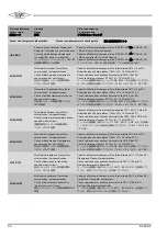
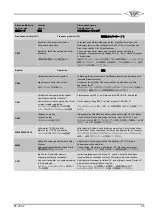
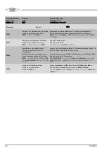
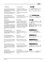
Störungs-Meldung
Failure code
故障コード
Ursache
Cause
原因
Störungsbehebung
Troubleshooting
トラブルシューティング
Frequenzumrichter (FU)
Frequency inverter (FI)
周波数インバーター(
FI
)
C500
Keine BUS-Kommunikation zum FU
No BUS communication to FI
FI
とのバス通信がない
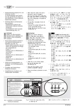
Datenkabel (Klemmleisten CN7: 2/3 & CN6: 8 an B1 & N1: 1/2/4) und
Spannungsversorgung des FU (K1: 2/4/6, N1: L1/L2/L3) prüfen.
Datenkabel und gegebenenfalls FU austauschen.
Check data cable (terminal strips CN7: 2/3 & CN6: 8 at B1 & N1: 1/2/4)
and power supply of FI (K1: 2/4/6, N1: L1/L2/L3). Replace data cable or
FI if necessary.
データケーブル(端子ストリップ
CN7
:
2/3 & CN6
:
B1
の
8 & N1
:
1/2/4
)
と
FI
の電源(
K1
:
2/4/6
、
N1
:
L1/L2/L3
)を点検してください。
必要に応じてデータケーブルまたは
FI
を交換してください。
C508
Kurzschluss im Stromkabel FU -
Verdichter
Short circuit in electric cable FI –
compressor
FI -
コンプレッサー間の電気ケーブルの
短絡
Kabel zwischen FU (N1: 1/2/3) und Verdichter (M1: U/V/W) überprüfen.
Check cables between FI (N1: 1/2/3) and compressor (M1: U/V/W).
FI
(
N1
:
1/2/3
)とコンプレッサー(
M1
:
U/V/W
)間のケーブルを点検
してください。
C509
Interne Störung des FU
Internal failure of FI
FI
の内部故障
Spannungszufuhr des FU 10 min. unterbrechen. Erneut einschalten.
Ggf. FU austauschen.
Disconnect supply voltage of FI for 10 min. Restart. Replace FI if nec.
FI
の電源を
10
分間外してから再度オンにし、必要に応じて
FI
を交換し
てください。
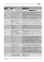
C510
Erdschluss in Stromkabel FU - Verdichter
oder im Verdichter selbst.
Earth fault in electric cable FI -
compressor or in compressor itself.
FI -
コンプレッサー間の電気ケーブル
またはコンプレッサー自体のアース接続
の異常
Isolierung des Kabels FU - Verdichter und Isolationswiderstand des
Verdichtermotors überprüfen.
Check insulation of the cable FI - compressor and insulation resistance
of compressor motor.
FI -
コンプレッサー間のケーブルの絶縁とコンプレッサーモーターの絶
縁抵抗を点検してください。
C511
Überstrom am FU
Overcurrent at FI
FI
での過電流
Betrieb außerhalb Verdichter-Einsatzgrenzen oder ggf. Verdichter defekt.
Spannungszufuhr des FU 10 min. unterbrechen. Dann erneut
einschalten. Betriebsbedingungen prüfen, ggf.Verdichter austauschen.
Operation beyond compressor application limits or compressor
damaged. Disconnect supply voltage of FI for 10 min. Then restart.
Check operating conditions, replace compressor if necessary.
コンプレッサーの適用制限を超えた運転、またはコンプレッサーの損傷。
FI
の電源を
10
分間外してから、再度オンにしてください。運転状態を
点検し、必要に応じてコンプレッサーを交換してください。
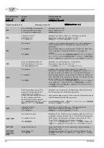
C512
Verdichtermotor zu heiß
Compressor motor too hot
コンプレッサーモーターの過熱
Motorkühlung, Druckgas-Temperaturfühler und Ölstand überprüfen.
Check motor cooling, discharge gas temperature sensor and oil level.
モーター冷却、吐出ガス温度センサーとオイルレベルを点検してください。
C513
FU überlastet / zu warm
FI overloaded / too hot
FI
の過負荷
/
過熱
Befestigung FU am Verdichter prüfen. Spannungszufuhr des FU 10 min.
unterbrechen. Dann erneut einschalten.Ggf. FU / Verdichter
austauschen.
Check fixing of FI at compressor. Disconnect supply voltage of FI for
10 min. Then restart. Replace FI ou compressor if necessary.
コンプレッサーの
FI
固定部を点検してください。
FI
の電源を
10
分間外
してから再度オンにし、必要に応じて
FI
またはコンプレッサーを交換し
てください。
C514
FU hat unzulässige Unterspannung.
FI has unpermitted under-voltage.
FI
で許容されない電圧低下が発生。
Netzspannung ist zu niedrig.
Supply voltage is too low.
供給電圧が低すぎます。
Summary of Contents for ECOSTAR LHV6/2DC-3.F1
Page 11: ...KT 200 2 11 violett violet blau blue braun brown grau grey rosa pink...
Page 44: ...44 KT 200 2...
Page 45: ...KT 200 2 45...
Page 46: ...46 KT 200 2...
Page 47: ...KT 200 2 47...


