background image

BITalino Mini 

User Manual  


 12 of 

24 


regulators are used to power the analog and the digital components of the device at 3.3V, VCC 
and DVCC. 
 

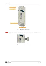
2.8.1. Charging the BITalino 

The BITalino Mini has a built-in charging circuit designed to safely charge up the Li-Po batteries 
that it uses. To charge the battery, connect the micro-USB cable provided with the BITalino 
Mini to the micro-USB port of the board and plug it to any USB 5V port. Note that the BITalino 
must be turned OFF for the battery to charge. It takes about 1h to charge the BITalino Mini 
standard 240mAh battery. 
 

2.9. Analog to Digital Converter 

The BITalino Mini uses the Analog to Digital Converter (ADC) embedded in the ATMega328PB 
Microcontroller unit with the following characteristics: 

  10-bit resolution 

  8 channels 

  ±2LSB Absolute Accuracy 

  0 - V

CC

 ADC Input Voltage Range 

 
Its embedded firmware however exploits this peripherical in such a way that it allows up to 6 
analog channels in acquisition with the following configurations: 

  6 Analog channels acquiring: 

o

  10-bit resolution for channels A1 to A4. 

o

  6-bit resolution for channels A5 and A6. 

  5 Analog channels acquiring: 

o

  10-bit resolution for the first 4 channels. 

o

  6-bit resolution for the last channel. 

  4 or less Analog channels acquiring: 

o

  10-bit resolution in every channel. 


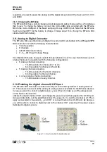
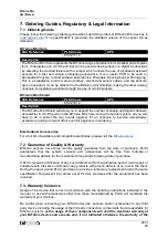
2.10. Enabling the digital channel UC-E6 port 

The BITalino Mini Solo has one built-in UC-E6 port connected by default to analog channel 
A1. This allows to connect all the variety of analog sensors available for the BITalino devices. 
In case you want to connect a digital sensor, you will have to make use of the jumper pads 
on the back of the board to 
activate the digital channel I1/O1 and change the power source that supplies the UC-E6 port.  
Using a hobby knife, cut the pads that connect the power to V

CC

 and the channel to A1. Then, 

apply some solder to the pads D

VCC 

and I1O1 to connect them to the UC-E6 port. By doing so, 

you will be able to connect a digital sensor to the channel I1O1 powering it the power supply 
dedicated to digital sensors. 


Figure 10 - How to enable the digital channel 

Summary of Contents for Mini Shield

Page 1: ...BITalino Mini User Manual...

Page 2: ...d of the possibility of such damages ATTENTION Please read this datasheet before using your BITalino sensor The information contained in this document has been carefully checked and were made every ef...

Page 3: ...BITalino 12 2 9 Analog to Digital Converter 12 2 10 Enabling the digital channel UC E6 port 12 3 Using the BITalino Mini with OpenSignals 13 3 1 Configuring your device in OpenSignals r evolution Wind...

Page 4: ...ns in mm 9 Figure 9 BITalino Mini Shield Dimensions in mm 10 Figure 10 How to enable the digital channel 12 Figure 11 Access the OpenSignals r evolution device manager 13 Figure 12 Enabling the device...

Page 5: ...ino Mini Solo to a breadboard for electronic instrumentation procedures and sensor development To make more channels available as an out of the box version you can upgrade your BITalino Mini SOLO by a...

Page 6: ...back Human Computer Interaction Academic projects OEM solutions Biomedical engineering instrumentation Biomedical device prototyping Robotics Cybernetics Physiology studies Hobbyists Biosignals enthus...

Page 7: ...BITalino Mini User Manual 7 of 24 2 Hardware layout and configuration 2 1 Block diagram Figure 3 Block diagram 2 2 Pinout diagram 2 2 1 BITalino Mini Solo Figure 4 BITalino Mini Solo Top View...

Page 8: ...lino Mini User Manual 8 of 24 Figure 5 BITalino Mini Solo Bottom View NOTE For devices with version number V 200828 h h h h h b ABAT c c DVCC h h h h h b A7 c c ABAT Figure 6 BITalino Mini Solo Label...

Page 9: ...BITalino Mini User Manual 9 of 24 2 2 2 BITalino Mini Shield Figure 7 BITalino Mini Shield Top View 2 3 Mechanical Drawings Figure 8 BITalino Mini Solo Dimensions in mm...

Page 10: ...ser of a low battery level By default the LED will turn on solid orange when the battery voltage reaches 3 4V However the firmware is ready to receive an order to adjust this threshold Such can be eas...

Page 11: ...on enabling the SPI peripheral please refer to the ATMega328PB datasheet6 2 7 Jumper pads On the back of the board five jumper pads can be found These were implemented to enable extra features of the...

Page 12: ...acquisition with the following configurations 6 Analog channels acquiring o 10 bit resolution for channels A1 to A4 o 6 bit resolution for channels A5 and A6 5 Analog channels acquiring o 10 bit reso...

Page 13: ...and opening the software in your computer Open the device manager of Opensignals to access and configure your BITalino device Figure 11 Access the OpenSignals r evolution device manager If the device...

Page 14: ...ing is as desired make sure the device is activated and the acquisition can start The device is activated for acquisition if the ENABLE button is blue Click on the record button in the OpenSignals mai...

Page 15: ...ree To use your BITalino Mini with your mobile device start by installing the android application and opening it Figure 15 Home screen Turn on y c ck h c b y do not have your Bluetooth connection alre...

Page 16: ...in range will appear on the main screen displaying its MAC address Select the one you want to connect to configure its settings and start the acquisition Figure 18 Devices found In the configuration s...

Page 17: ...ser Manual 17 of 24 Once all the settings are as desired click on the record button on the top right corner to start the acquisition Figure 20 Example of acquisition with an ECG sensor Figure 19 Devic...

Page 18: ...specifications compatible with those of the BITalino hardware you can connect any sensor and even your own custom designs You can also connect 1 bit digital input or output accessories e g switch Can...

Page 19: ...D c A F b EC g in Bioengineering 7 1 pp 16 2020 Daniel de la Iglesia Andr Mendes Gabriel Gonz lez Diego Jim nez Bravo and Juan de Paz Connected Elbow Exoskeleton System for Rehabilitation Training Ba...

Page 20: ...other approved accessories purchased from PLUX or by a PLUX agent The user should inspect the sensors on a regular basis to ensure that they remain in good working order The user should stop using the...

Page 21: ...Atmospheric pressure between 500hPa and 1060hPa Whenever the equipment needs to be transported it should be placed in the original box since this was designed and tested to ensure the equipment and ac...

Page 22: ...eader system all you will have to do is solder the two boards together for all channels to become immediately available requiring no major effort even for beginners in soldering Electrodes Accessories...

Page 23: ...periencing any problems that cannot be solved with the information given in the BITalino documentation Please send us an e mail with precise information about the error occurrence device configuration...

Page 24: ...plux plux info web http www plux info Headquarters Zona Industrial das Corredouras Lt 14 1 2630 369 Arruda dos Vinhos Portugal tel 351 263 978 572 fax 351 263 978 902 Lisbon Office Av 5 de Outubro n...

Reviews: