


MOTOR WIRING AND ELECTRICAL REQUIREMENTS
2. Connect leads to machine in a manner that will be approved by local electrical inspectors.
3. Rated voltage of the unit shall be identical with full supply voltage.
4. Voltage drop on the supply line shall not exceed 10% of full supply voltage.
5. The feederline conductor size in the raceway from the branch circuit to the unit must be correct to assure
adequate voltage under heavy starting and short overload conditions.
6. The feederline conductor shall only be used for the supply of one unit of the relevant horsepower. For
connections of more than one unit on the same feederline, a local electrician will have to be consulted to
determine the proper conductor size.
7. The size of the electrical wiring required from the power source to the
Single phase
mixer-grinder/chopper
is a
MINIMUM OF No. 10 GAUGE WIRE.
8. The BIRO Manufacturing Company is not responsible for permanent wiring, connection or installation.
PRE-OPERATION AND AUGER ROTATION CHECK
ROTATION MUST ONLY BE CHECKED WITH THE
GRINDING AUGER REMOVED, otherwise serious irreparable
damage may occur to grinding components.
1. Turn the hand/foot selector switch to the hand position. Push the green start button. CHECK THE
ROTATION OF THE AUGER DRIVE SHAFT; ROTATION MUST BE COUNTER-CLOCKWISE as
indicated by the rotation decal affixed to the grinding bowl.
2. If machine runs clockwise (backwards), it must be rewired to correct rotation, otherwise serious irreparable
damage may occur to the grinding components.
3. When supplied, check operation of optional pneumatic footswitch. Plug footswitch cord into female
coupling located on the same side as the operation controls. Move selector switch to foot. The machine will
operate with pressure on the footswitch bellow. Releasing the bellow stops the machine. The footswitch
operates the mix and grind together.
4. Insert auger assembly into grinding bowl, place knife (sharp edges out) onto the square end of the auger
assembly. The breaker plate slides over the worm knife drive pin, and is held from rotating by pins in the
grinder bowl. Install the retaining ring.
4
Three phase
grinders are wired 208/220 volts unless otherwise specified. Be sure motor specifications
(voltage, cycle, phase) match power supply line. Be sure voltage is up to specification.
The size of the electrical wiring required from the power source to the
Three phase
mixer-grinder/chopper
is a
MINIMUM OF No. 12 GAUGE WIRE.
1.
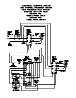
Single phase
grinders are wired 208/220 volts unless otherwise specified. Be sure motor variable
frequency drive parameters are adjusted for correct line voltage. Be sure to read line voltage for correct
parameter adjustment. See variable frequency drive manuals for parameter settings.
Summary of Contents for MINI-22
Page 2: ......
Page 16: ...13 OPERATOR S NOTES ...
Page 21: ...18 OPERATOR S NOTES ...
Page 22: ...19 ...
Page 23: ...20 ...
Page 24: ...21 ...
Page 26: ...OPERATOR S NOTES 23 ...


