Bird Technologies Manual 7-9570-1-1
(Rough Draft)
08/19/16 Page 12
sub carrier that links the remote unit to the master
unit.
Users have the ability to set the following parame-
ters in the remote unit via the web based GUI appli-
cation:
- Gain Values (UL & DL)
- ALC threshold (UL & DL)
- UL Test tone
Users cannot adjust/align any fre-
quency response, linearity response
or detector calibration levels.
The remote unit has a built in ALC (Automatic Level
Control) with preset levels, to make sure that the
linearity or spectral spreading does not exceed the
regulatory limits. The ALC threshold is a setable
value that defines what output power is allowed
from the remote unit. If an inserted signal plus the
set gain in the remote unit exceeds the set ALC
threshold the remote unit will automatically reduce
the gain so that the output signal level always
matches the set ALC threshold. The device cannot
end up in saturation due to the ALC feature. Satu-
ration or over-modulation is even prevented for
pulsed signal inputs. There are also configurable
signal threshold parameters in the remaining com-
ponents of the DAS system located in the master
unit.
UL Test Tone is a help feature tool used only when
commissioning the DAS network.
DL ALC threshold for the remote unit is 23 dBm
and cannot be exceeded.
WEB BASED GUI INTERFACE
When first connecting to the remote unit via the
web based GUI interface a system layout screen
will be presented as shown in
Figure 5
. The
screen will show all of the addressable boards con-
nected into the system. Master unit boards are
shown under the column titled Fiber optic Interface
and remote unit boards are shown under the col-
umn titled Remote. In this example there are four
FOI (Fiber Optic Interface) boards installed in the
master unit and one FOR (Fiber Optic Remote)
board installed in a remote unit. Sub carrier links
between the boards are shown as lines on the
screen display. To ease location and identification
each box shown presents the user defined system
name for the individual boards. Clicking on any of
the boxes will call up the GUI Interface screen for
that particular board.
Using the mouse to click on the FOR board shown
in the example will call up an overview screen for
that particular board as shown in
Figure 6
. This
screen provides a convenient summary of the
boards active alarms and RF status. A description
of any alarm events are listed as well as when the
alarm occurred. The RF status for all RF bands
built into the remote unit, in this example there are
4 bands.
NOTE
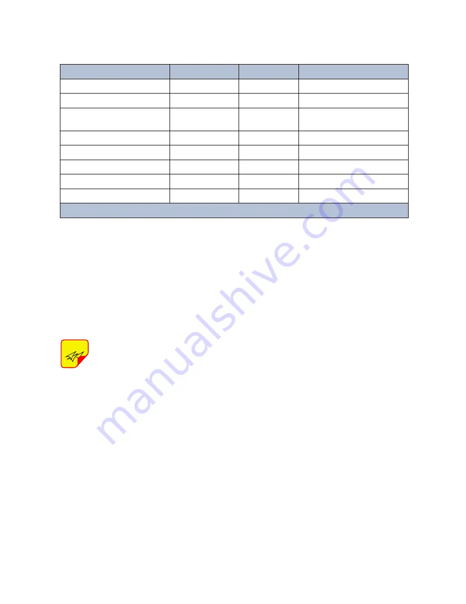
State
On LED
Alarm LED
Note
Booting
2 Hz
Off
Normal Boot
Booting standalone mode
2 Hz
2 Hz
Not attached to rack
Booting read of MAC address
failed
2 Hz
On
Error
Starting
0.1 Hz 90%
0.1 Hz 90%
Kernal startup
Operation
0.5 Hz 10%
Off
Normal operation
Operation
0.5 Hz 10%
1 Hz 10%
Minor alarm state
Operation
0.5 Hz 10%
2 Hz 25%
Major alarm state
Operation
0.5 Hz 10%
On
Critical alarm state
Table 3:
DDL front panel LED behavior.


