background image

1.

Affix the UV Warning Label, shown here, to 
the door or access panel used to service the 
unit.

Safety Components

Install Sight Glass

Install an Optional Light Switch

1.

To help prevent accidental exposure to UV light, Biozone can provide an optional 
on/off switch, to be installed by a licensed contractor on the circuit between the 
main power supply and the CoilCare power supply.  Electrical wire for the switch 
not provided.  

Contact BioZone for additional information.

2.

Record  the  installation  information  on 
the  UV  Warning  Label.  The  UV  Warning 
Label  contains  fields  convenient  to  record 
installation  and  service  information.  It  is 
recommended  to  record  installation  and 
service  details  on  the  UV  Warning  Label  as 
those functions are performed.

INSTALLATION INSTRUCTIONS

8

Install a UV Warning Label

Caution:  UV  light  that  can  cause  serious  eye  burns  and  temporary 

blindness.  Ensure  all  access  panels  have  been  replaced  and  doors 
closed before activating the system.

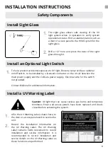
1.

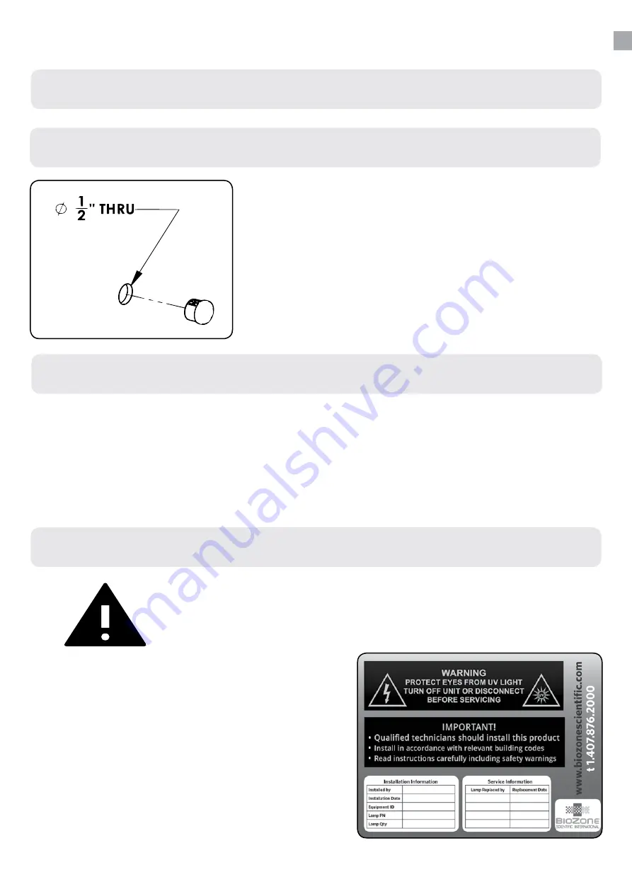
The  sight  glass  allows  safe  viewing  of  the  UV 
light  system  when  in  operation  to  verify  system 
operational status. Find a suitable location such as 
a door or access panel to the HVAC system for the 
sight glass.

2.

Drill  a  1/2”  hole  and  press  the  base  of  the  sight 
glass through it.

Summary of Contents for CoilCare Series

Page 1: ...COILCARE X 2017 BioZone Scientific International Inc 81200012B Installation Instructions and Operating Manual CoilCare Series...

Page 2: ...g efficiently The system is equipped with a UV lamp and a reflector to direct and focus UV light on the coil surface The water resistant power supply is easy to mount and can withstand the humid envir...

Page 3: ...veness expected at beyond 48in 1219mm radius from lamp center axis When coil depth is more than 12in 305mm treating both sides of the coil may be indicated 12 305 mm max space between lamps 6 152 mm m...

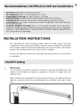
Page 4: ...tibility 4 Recommendations for Effective CoilCare Installations EMT Conduit In most situations when the system is mounted to surfaces perpendicular to the surface to be irradiated L brackets are attac...

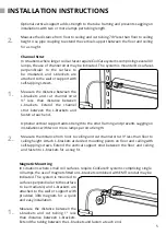
Page 5: ...t Use pipe coupling to extend the vertical support between the floor and ceiling for a snug fit Channel Strut In situations where larger coil surfaces require CoilCare systems comprising several UV la...

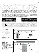
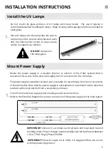
Page 6: ...of the HVAC system that is convenient for access to the electrical supply and for connection to the UV lamps The power supply is weather resistant and is suitable for mounting to the interior or exter...

Page 7: ...r handler and exterior for connections as needed INSTALLATION INSTRUCTIONS 7 1 Connect Lamps and Cables Arrangecablesasneededforinstallation Ifnecessary use the Optional 3 4 or 1 cable strain relief t...

Page 8: ...g Label The UV Warning Label contains fields convenient to record installation and service information It is recommended to record installation and service details on the UV Warning Label as those fun...

Page 9: ...DISCONNECT BEFORE SERVICING OPERATION AND MAINTENANCE 9 As needed periodically wipe the UV lamps with a clean cloth or alcohol swab to remove any accumulated dust or dirt This process should be perfor...

Page 10: ...ow after they have exceeded their rated lifespan however their germ killing effectiveness diminishes with time so they must be replaced on schedule for the system to function properly Contactyourlocal...

Page 11: ...tional Inc are used with this equip ment Consequential and incidental damages are not recoverable under this warranty Manufacturer assumes no liability for any harm which may occur as a result of the...

Page 12: ...low 80 F 27 C UV output can decrease by as much as 50 Cooling effects are noted and are factored into CoilCare system design Reflectance Ultraviolet light can be reflected off of surfaces the degree o...

Reviews: