35
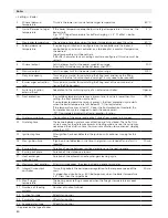
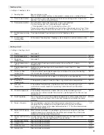
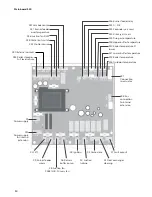
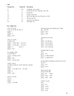
Fuses
Designation
Rating [A]
Description
F1
0.25
Transformer main board
F2
5
Suction fan (X8), burner feeder worm (X9)
F3
10
Ignition (X5)
F4
10
Suction turbine (X4)
F5
10
Heat exchanger cleaning (X2), grate unit (X3)
F6
10
Return pump (X6)
F7
2.5
Lambda sensor heating
F8
2.5
24V power unit
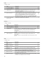
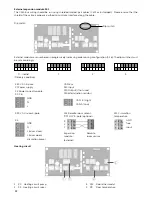
Pin configuration
230 V AC 3-pole
X1, X2, X4, X5, X6, X8, X9, X10
L
N
GND
230 V AC 4-pole
X3 Grate drive
L (Grate close) Wire Nr. 2
L (Grate open) Wire Nr. 3
N Wire Nr. 1
GND
No-voltage 3-pole
X7 Fault output
normally closed
Root
normally open
230VAC 4-pole
X11 Power supply for internal extension modules
L
L switched via STL – not used
N
GND
230 V AC 2-pole
X12 STL
L
L switched
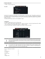
Temperature sensor/analogue input 2-pole
X13 – X18, X23
Input
GND
Lambda sensor 4-pole
X21
Input positive
Input negative
Sensor heating
Sensor heating
Analogue output 3-pole
X26
24 V
Analogue output
Analogue GND
Burner feeder overtemperature/external contact
X27, X30
24 V
Input
Digital input 3-pole
X28, X32, X35, X36
24V brown
Input black
GND blue
CAN Bus 4-pole
X38
24 V
CAN A
CAN B
GND
Summary of Contents for Top Light Zero 18
Page 38: ...38 08 Notes ...
Page 39: ......

