PRODUCT SHEET
www.biopac.com
BIOPAC Hardware |
BioNomadix Series
| Page 6 - 26
Updated: 8.18.2020
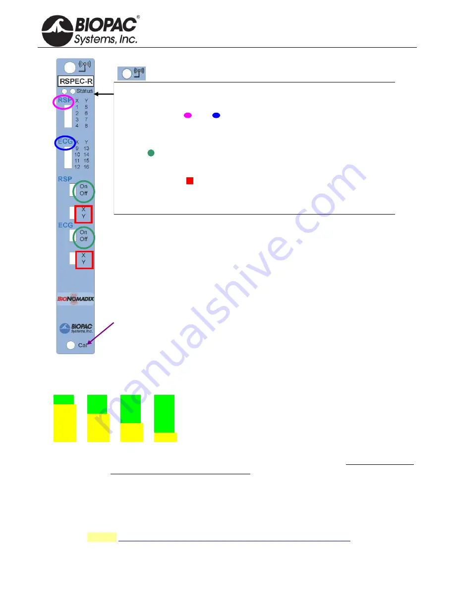
The
RSPEC
Receiver unit is depicted, but controls operate similarly for all units.
Wireless antenna input
Receiver LED:
Steady green when paired with transmitter. Blinks amber once per
second when communication is interrupted.
Input Signals:
A =
B =
“
A
”
Assigns the input signals for channels 1-8.
“
B
”
Assigns the input signals for channels 9-16.
On/Off
Enables or disables module channels:
“
A
”
channels 1-8
“
B
”
channels 9-16.
X/Y channel banks
Selects between “X” channel bank or “Y” channel bank.
“
A
” X
bank is 1-4,
Y
bank is 5-8.
“
B
” X
bank is 9-12,
Y
bank 13-16.
NOTE:
“
A
” or “
B
” banks that are turned off will free up those associated Analog
channels for use by other signal types.
Cal
:
Recessed Calibration button.
NOTE
: Calibration is not required, most users
can use factory presets. Calibration is an advanced procedure.
TRANSMITTER BATTERY LIFE
Transmitter battery life is described below as a change of color in the sequence of LED flashes.
LED Color Pattern
Charge %
green
green
green
green
75% - 100%
yellow
green
green
green
50% - 75%
yellow
yellow
green
green
25% - 50%
yellow yellow
yellow
green
5% - 25%
yellow
yellow
yellow
yellow
< 5%
IMPORTANT:
If the transmitter is to be stored for prolonged periods, it is strongly recommended that the
battery be fully charged and the transmitter turned off prior to storage. Failure to do so may
result in permanent damage to the battery.
SOFTWARE SETUP
Recording data with AcqKnowledge software
After completing setup, click Start in the Acq
Knowledge
software to begin recording data.
If the paired signal is interrupted due to electrical interference or a subject wandering out of range, the most
recently-acquired data point will be retained, with normal acquisition continuing once communication is
reestablished. See also:
BioNomadix Operational Range and Transmission Characteristics


