Biomorph Flexo Corner Assembly Download Page 15

15

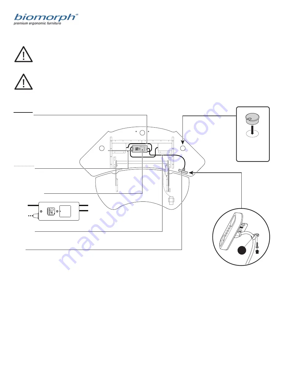
Cable Diagram Corner

IMPORTANT: 

All cables must be tacked up and made neat with supplied cable guides. NO cables may hang down ex-

cept those passing through cable chains. Make sure cables have enough slack between surfaces to allow 

full height adjustment between surfaces. 

IMPORTANT: 

Extend desktops to full opposite heights to ensure that cables will travel w/o stress).

GROMMET HOLE

Place grommet into

grommet hole. Route

cable accordingly.

POWER CABLE

Connect power cables to power

strips inside cable cabs.

WIRE CLIP

A wire clip MUST be placed directly 

behind switch to prevent cable droop

l

LONG CABLES

Use LONG cables to connect both 

legs to ports #1 & #2  in controller box.

CABLE TRACKS

Red FRONT surface

Blue REAR surface

SWITCH

for FRONT surface use long 45˚ angle bracket.

Control switches connect to port A1.

2 PORT CONTROLLER

box for FRONT surface

SWITCH

POWER CABLE

LONG CABLE/

FRONT LEG

LONG CABLE/

FRONT LEG

2
DC

AC

3

4

1

A2

A1

Summary of Contents for Flexo Corner

Page 1: ...Flexo Level3 Desk Flexo Corner Assembly Biomorph Inc 1045 33rd Street South St Cloud MN 56301 Tel and Fax 888 302 3375 info biomorphdesk com www biomorph com SX2M A LL S DS SX2M A LL B DS ...

Page 2: ... 2 Port Control Box Qty 1 Wire Clips Qty 62 Cable Cab Qty 2 45 Digital Readout Switch and 45 Switch Bracket Qty 1 a LH Top Plate Qty 1 b RH Top Plate Qty 1 c Keyboard Mechanism Qty 1 n i j m k Foot Qty 2 d Table Top Qty 1 or h Table Top Corner Qty 1 h1 Adjustable Crossbar Qty 1 g LH Adjustable Crossbar Section Qty 1 e RH Adjustable Crossbar Section Qty 1 f RH Adjustable Crossbar Section for Corner...

Page 3: ...his procedure is not followed then tops will not line up with frame DO NOT REMOVE PROTECTIVE MATERIAL FROM TOPS UNTIL FINAL ASSEMBLY IMPORTANT When moving this desk do not drag frame as it can cause leg actuators to bind and fail Always lift off floor using frame not tops a a c b d d g g1 e e1 f f1 e1 f1 g1 e f g Replaces for Corner application only ...

Page 4: ...4 Leg Assembly continued Glide Qty 4 M6 x 12 Screw Qty 8 a a d d Note Longer end of Foot must face toward front user side 2 Leg Assembly M6 x 12 Screw Qty 4 1 b c a a b c a ...

Page 5: ...5 Leg Assembly continued e f e1 f1 M6 x 12 Screw Qty 4 3 LH Side RH Side e Use these holes Use these holes f ...

Page 6: ... these holes Use these holes e 72 LH Side 60 LH Side M6 x 12 Screw Qty 4 M6 Flange Head Nut Qty 4 4 g Use these holes Use these holes e g 84 LH Side 72 RH Side 60 RH Side 84 RH Side Use these holes Use these holes e g g g g f f f g f e ...

Page 7: ...7 Crossbar Assembly for Corner continued Use these holes Use these holes e1 Corner LH Side M6 x 12 Screw Qty 4 M6 Flange Head Nut Qty 4 5 1g Corner RH Side g1 f1 f1 e1 g1 ...

Page 8: ...8 Top Assembly 5 x 25mm Wood Screw Qty 12 h ...

Page 9: ...9 Top Assembly Corner 5 x 25mm Wood Screw Qty 12 h1 ...

Page 10: ...10 Electrical Components j 45 Digital Readout Switch and 45 Switch Bracket Qty 1 16mm PH Wood Screw Qty 2 i 2 Port Control Box Qty 1 45mm PH Wood Screw Qty 2 j ...

Page 11: ...11 Cable Management k Cable Cab Qty 1 16mm PH Wood Screws Qty 6 k ...

Page 12: ...12 16mm PH Wood Screws Qty 8 Keyboard Mechanism Installation ...

Page 13: ...13 1 1 2 Black Hex Head Nut Bolt Qty 8 Keyboard Mechanism Installation continued ...

Page 14: ... grommet into grommet hole Route cable accordingly POWER CABLE Connect power cables to power strips inside cable cabs CABLE CAB Optional Place door towards user WIRE CLIP A wire clip MUST be placed directly behind switch to prevent cable droop l LONG CABLES Use LONG cables to connect both legs to ports 1 2 in controller box CABLETRACKS Red FRONT surface Blue REAR surface SWITCH for FRONT surface u...

Page 15: ...stress GROMMET HOLE Place grommet into grommet hole Route cable accordingly POWER CABLE Connect power cables to power strips inside cable cabs WIRE CLIP A wire clip MUST be placed directly behind switch to prevent cable droop l LONG CABLES Use LONG cables to connect both legs to ports 1 2 in controller box CABLETRACKS Red FRONT surface Blue REAR surface SWITCH for FRONT surface use long 45 angle b...

Page 16: ...een reached The system will return to normal operation and give a short blink after 5 seconds of inactivity on the keys 2 Keep the button pressed until the position is reached Release button and press again to go past that position Press one of these memory buttons and the system will start driving to the pre programmed memory position 1 2 Display function only included on dual or multiple drive t...

Page 17: ...10 times to remove all voltage from the system Wait 30 seconds and re plug all connections back in to ensure good connections with all electrical parts and repeat the above process At this point the table should adjust up and down freely If you have a dual surface desk then this procedure must be done with both surfaces using the button If the surface s will not move at all after the above procedu...

Reviews: