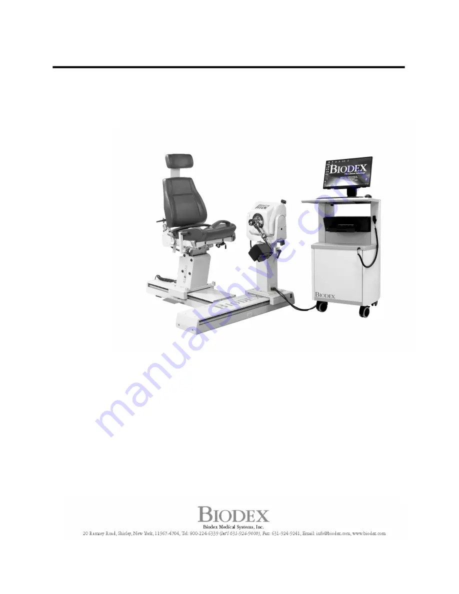
BIODEX MULTI-JOINT SYSTEM
INSTALLATION INSTRUCTIONS
840-000
840-000-10
840-000-30
850-000
850-000-10
850-000-30
FN: 08-051-CLR Rev A 9/19
Page 1: ...BIODEX MULTI JOINT SYSTEM INSTALLATION INSTRUCTIONS 840 000 840 000 10 840 000 30 850 000 850 000 10 850 000 30 FN 08 051 CLR Rev A 9 19...
Page 2: ...request or directly from the Biodex website http www biodex com If the desired information is not found please feel free to contact a local distributor or Biodex directly at supportservices biodex com...
Page 3: ...mbols 4 1 Installation Instructions 6 Tools Required 6 Installation Procedure 6 Monitor Install Procedure 8 Cabling for CDS Power Receptacle 8 Seat Lift Power Connection 10 AC Input Receptacle Power C...
Page 4: ...4 Definition of Symbols The following symbols and their associated definitions are used and implied throughout this manual...
Page 5: ...ns System Power Requirements Provide 220 VAC 60 Hz 20 amp dedicated electrical service with dedicated ground Locate within ten feet of ear of the T base Receptacle will be a single Hubbell IG 5461 rat...
Page 6: ...he chair on top of the chair T base Align the holes and use a 5 16 Allen wrench to tighten Be careful not to slide the chair around too much as this may cause the paint to scratch 13 Remove the dynamo...
Page 7: ...7 Figure 1 1 Multi Joint System Cart and Monitor from the Rear...
Page 8: ...cedure Figure 1 2 Rear View of the CDS Cart Cabling for CDS Power Receptacle Figure 1 3 Power Receptacles on the Back of Seat CDS Cart Power Receptacle Seat Lift Power Receptacle 195 to 245 Volt AC In...
Page 9: ...e Screws from the CDS Cart Power Receptacle Figure 1 5 Loosen the Clamp on the Cable Figure 1 6 Cable Positioned at CDS Cart Power Receptacle 1 Strain Relief Slot Facing Up Cable Clamp Strain Relief S...
Page 10: ...Cart Power Receptacle Seat Lift Power Connection Figure 1 8 Loosen the Cable Clamp Screw and Replace the Clamp on the Cable Figure 1 9 Seat Lift Receptacle 1 Seat Lift Receptacle 1 2 3 Strain Relief...
Page 11: ...t Lift Power Cord AC Input Receptacle Power Connection Figure 1 11 Loosen the Clamp on the Cable Figure 1 12 Loosen the Cable Clamp Screw and Remove the Strain Relief Cable Clamp Screw Seat Lift Power...
Page 12: ...12 Figure 1 13 Removing the Screws from the AC Input Receptacle Figure 1 14 Installing the AC Input Cable 3 3 1 2 Cable Clamp Screw...
Page 13: ...STATE CONTACT AT SITE PHONE FAX Biodex Representative Installation Start Time Serial Number Model Number Software Version Firmware Version Biodex Contacts 1 800 224 6339 Software Support ext 2120 Tech...
Page 14: ...pauses both on the dynamometer and hand held and rotate buttons on the dynamometer Comments 6 In the reactive eccentric mode check speeds and torque limits Comments 7 In the isokinetic mode check spee...
Page 15: ...nctioning properly The Biodex representative has instructed the facility on startup hardware and software The facility is capable of proper operation of the Biodex System BIODEX REPRESENTATIVE DATE Si...
Page 16: ...16...