


EN - 12
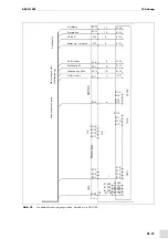
5 Functional description
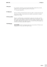
BRS-LCi PLC
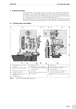
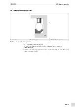
5.2 Injection jig
1
The welding torch moves into the cleaning position
2
The control box (HAN 3AQ5: PIN5=24 V) queries the ready signal
3
Once the ready signal is available, the start signal can be set (HAN 3AQ5: PIN5=24V- XS1)
4
Once cleaning is complete, the ready signal is sent from the control box to the robot
5
Injection via 24 V signal on HAN 3AQ5: PIN2
The injection period is specified by the robot.
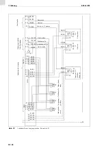
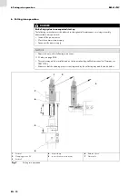
The anti-spatter fluid volume can be set as required using an adjusting screw
.
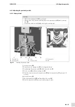
1
Anti-spatter fluid adjusting screw
2
Flow control valve for adjusting the anti-spatter fluid
3
Venturi valve
4
Transmitter disc
5
5/2 directional valve for
injection unit (on/off)
Fig. 5
Reamer injection jig
1
2
3
4
5
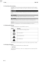
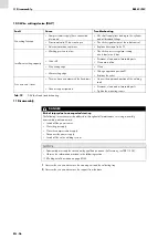
WARNING
Risk of crushing
Limbs can be drawn in and crushed by moving parts (reamer, clamping unit).
• Keep your hands away from moving parts.
WARNING
Damage to the eyes
When injecting the anti-spatter fluid, spray mist can form that can damage the eyes.
• Wear safety goggles.
• Only adjust the anti-spatter fluid by opening the solenoid valve Y4.
Summary of Contents for BRS-LCi SPS
Page 4: ...DE 4 1 Identifikation BRS LCi SPS ...
Page 34: ...EN 4 1 Identification BRS LCi PLC ...
Page 64: ...FR 4 1 Identification BRS LCi API ...
Page 94: ...ES 4 1 Identificación BRS LCi PLC ...
Page 123: ...BRS LCi PLC Notas ES 33 Notas ...


