I
NSTALLING THE
BinGO!
7
put of 5V–/800mA. These two supplies are not inter-
changeable.
The two RJ-45 cables included with your BinGO! are
identical, and can both be used for connecting BinGO! to
the ISDN as well as the ethernet.
LED Indicators
Each time you power up the system, the BinGO! switches
into
Power Up Mode
and performs a self-test to verify the
integrity of the system. The LEDs on the front panel cor-
respond to various stages of the test.
Upon successful completion of the self test, the BinGO!
then switches into
BOOTmonitor Mode
, (the right three
LEDs remain on) as described in the
User’s Guide.
If the ERR indicator remains on (see table below) there
may be a problem with the cabling. Verify the ISDN and
LAN cabling is correct and power up the system again.
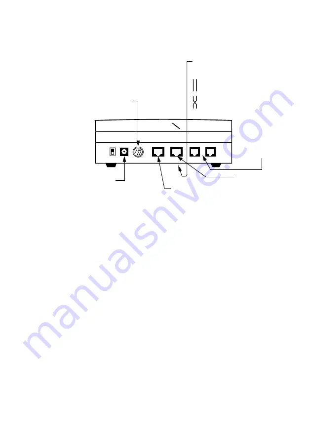
Step 1
Connect the included laplink
cable to your terminal or
computer and the 8 pin serial
port of BinGO!.
Step 5
Connect the included
ISDN cable (RJ-45) to
the S
0
port of BinGO!
and your ISDN outlet.
Step 6
Connect the included
power supply to the BinGO!
and your mains socket.
Switch your BinGO! on with
the power switch.
Step 4
Connect the
10Base-T port of
your BinGO! to
your ethernet or
PC using the
included cable.
Step 2
Set the LAN switch on the under-
side of your BinGO! to position:
if you want to connect BinGO!
to your LAN (MDI)
if you want to connect BinGO!
directly to the ethernet board
of your PC (single user system)
(MDIX)
POWER
SERIAL
ISDN-S/T
LAN
✆
PHONE
1
10BASE-T
2
I
0
Step 3
Connect your
analog equip-
ment to Phone
ports 1 and 2.
☞


