Replaces
Part Sheet
77-2709R-10
Part
Sheet
77-2709R-11
Binks Model 7N
Spray GuN
Binks Model 7N Gun is a rugged, light weight, hand held
Spray Gun, for applying gel-coats and polyester resins.
Catalyst is introduced to the material stream through the
atomizing air as the resin flows from the Material Nozzle.
Flow rate of the Gun varies up to 2 GPM depending on
nozzle selection. The actual fluid output is controlled by
nozzle orifice size and fluid pressure.
Nozzle TyPeS
Internal Mix—Low to high material volume,
low air consumption.
External Mix—Low material volume, fine
atomization.
Spray patterns are determined by the nozzle selection and
vary somewhat depending on size, angle, nozzle orifice and
output. External mix nozzle pattern cannot be changed
because this gun does not have a side port control.
However, its spray fan pattern can be rotated through 360°
by loosening the Retaining Ring, and rotating the Nozzle
Body, Item 1.
Faulty spray patterns can be caused by:
1. Foreign material in Air and/or Fluid Passages.
2. Viscosity too high for spraying. Air supply
or pressure inadequate.
3. Worn or damaged Nozzle surfaces.
4. Gellation in Gun Head Air Passages.
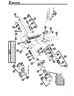
5. Gun Head Check-Valve, Items 6, 7, 8 frozen.
GuN CleaNiNG
Submerging the Gun in solvent will not harm the Gun;
however, it can adversely affect the Nozzle “O” Ring, Item
2. Submerging is poor practice because of the solvent resi-
due that may cling to interior air passages. Clean solvent
MUST be used if the Gun is to be submerged. The best
practice is to remove the Air Nozzle and to flush solvent
through the fluid passages. All Nozzles may be placed in
solvent for washing. The Nozzle Orifice and angle passage
ways are critical. Always wash and rinse with a clean sol-
vent to prevent residue accumulation in the minute holes.
NEVER use metal instruments for cleaning.
CheCk-ValVe CleaNiNG
A Check-Valve in the Head of the Gun prevents resin from
backing up into Air/Catalyst Passage. However, resin build-
up periodically may cause the Ball to freeze in the Head.
To free Ball:
1. Remove Plug, Item 11, Fluid Needle Assembly,
Item 16, and Packing Nut, Item 38.
2. Insert Wrench, Part No. 73-165, and turn counter-clock-
wise to remove Head, Item 5, and Check-Valve
Components, Items 6, 7, and 8.
3. Clean as required and reassemble.
Exterior surfaces of Gun should be kept clean by
wiping with a solvent-wet cloth.
ReSiN PaCkiNG
Packing take-up is accomplished by tightening Packing
Nut, Item 38, with a wrench. Packing replacement is
simple; proceed as follows:
1. Remove Fluid Control Screw, Item 17.
2. Remove Needle Assembly, Item 16.
3. Remove Packing Nut, Item 38, and old Packing,
Item 37, from Cavity.
4. Insert new Packing in Cavity.
5. Reassemble items removed in (1), (2) and
(3) above.
6. Set Packing, Item 37, by tightening Packing Nut,
Item 38, until Needle movement, Item 16, is
resisted, then loosen approximately 1/2-3/4 turn.
aiR leakS:
Through Gun head
1. Leaky Air Valve, Item 28.
Inspect, clean, or replace.
2. Air Valve Body, Item 30, not seated. Tighten.
3. Air Valve Body Gasket, Item 26, missing or damaged.
Replace.
4. Damaged Seat surface in Gun Body, Item 22. Replace.
at air Catalyst Valve, item 28
1. Around Air Valve Stem, Item 29. Tighten or replace
Packing, Item 31.
2. Damaged Air Valve Stem. Inspect and replace if
necessary.
3. Damaged Seat surfaces. Attempt repair with PTFE tape.
Replace if necessary.
NOTE
Needle lock Nuts, on the 59SS Needle, must be first removed
from the rear of the Needle, and the Needle then extracted
from the head end of the Gun. The 68SS Needle can be pulled
out from the rear of the Gun.
Summary of Contents for 7N
Page 7: ...NOTES 7 ...


