background image

4

VRF180913 Rev. A

www.bindicator.com

4

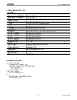
TECHNICAL SPECIFICATIONS

FUNCTIONAL

Power Requirements Universal

(± 10%), 120-240 VAC 50/60 Hz or 24-48 VDC

Power Consumption - STANDARD

10 W AC; 3 W DC

Power Consumption - ADVANCED

11 W AC; 4 W DC

Fuse 

Slow Blow, 1A 300 V (Not User Serviceable)

Operating Temperature

Electronics

-40° to 158° F (-40° to 70° C)

Probe

-40° to 993° F (-40° to 534° C) depending on probe

Outputs

Main Relay

8 A DPDT @ 240 VAC or 30 VDC (resistive)

Auxiliary Relay - ADVANCED ONLY

0.46 A SPDT @ 150 VAC or 1 A @ 30 VDC

PERFORMANCE

Pressure Rating

150 psi (10.5 kg/cm

2

) with 

3

/

4

” NPT; 50 psi (3.5 kg/cm

2

) with 1

1

/

4

” NPT

Time Delay - STANDARD

Field Adjustable; 0.2-6 seconds

Time Delay - ADVANCED

Field Adjustable; 0-150 seconds

Fail Safe

Field Selectable; high/low level

Sensitivity - STANDARD

Field Adjustable; minimum 1.5 pf

Sensitivity - ADVANCED

Field Adjustable; minimum 0.5 pf

Maximum Particle Size

9

/

16

” (14.3 mm)

PHYSICAL

Enclosure Material

Polyester or Epoxy Coated Aluminum or 304 SS

Dual Conduit Entry

3

/

4

” NPT or M20 x 1.5

Extended Pipe Material

Galvanized or 316 SS

Shipping Weight

Integral, non-extended 10 lb (4.5 kg)

Pollution Degree

2

Installation Category

II

Altitude

6,562 ft (2,000 m)

APPROVALS & RATINGS

UL (US and Canada):

Ordinary Location Type 4X; IP66
Hazardous Location, Type 4X; IP66 (Pending)
 

Explosion Proof


Dust Ignition Proof

ATEX/IECex (Pending):

Dust and Gas Categories

CE

Electromagnetic Compatibility Directive
Low Voltage Directive

Summary of Contents for VRF II Series

Page 1: ...IOMVRF180713 Rev A VRF II Series Installation Operation Manual IOMVRF180913 Rev A ...

Page 2: ......

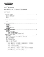
Page 3: ...l Safety Disconnect Requirements for Permanently Installed Equipment Protective Earth Ground Electrical Connections Conduit Cable Connection VRF II Series Integral Model Only VRF II Series Remote Model Only Figure 3 VRF II Series Integral Enclosure with Cover Removed STANDARD Figure 4 VRF II Series Integral Enclosure with Cover Removed ADVANCED Figure 5 Power and Ground Connections Figure 6 Main R...

Page 4: ...ENT VI SET UP 13 Operation Product Overview STANDARD Figure 11 Switch Functions Product Overview ADVANCED Figure 12 Switch Functions Pro Guard Fail Safe Selection Time Delay Settings STANDARD Time Delay Settings ADVANCED Sensitivity Settings STANDARD Sensitivity Settings ADVANCED Calibration Automatic Calibration Manual ADVANCED ONLY Calibration Test ADVANCED ONLY Figure 13 Magnetic Fob VII MAINTE...

Page 5: ...d companies and must not be disposed of in a municipal collection site If you do not have the means to dispose of properly please contact for return and disposal instructions or options STORAGE If the device is not scheduled for immediate installation following delivery the following steps should be observed 1 Following inspection repackage the unit into its original packaging 2 Select a clean dry...

Page 6: ...nstrument is used according to the specifications described in this document For safety and warranty reasons use of accessory equipment not recommended by the manufacturer or modification of this device is explicitly forbidden All servicing of this equipment must be performed by qualified service personnel only This device should be mounted in locations where it will not be subject to tampering by...

Page 7: ...round When there is a large enough change in the impedance the status of the output relay changes to indicate the presence or absence of the material APPLICATIONS This model is ideal for the point level detection of dry bulk materials liquids and slurries It is not appropriate for conductive materials that will coat or build up on the probe It is ideal in the measurement of materials with a dielec...

Page 8: ...Standard Field Adjustable 0 2 6 seconds Time Delay ADVANCED Field Adjustable 0 150 seconds Fail Safe Field Selectable high low level Sensitivity Standard Field Adjustable minimum 1 5 pf Sensitivity ADVANCED Field Adjustable minimum 0 5 pf Maximum Particle Size 9 16 14 3 mm PHYSICAL Enclosure Material Polyester or Epoxy Coated Aluminum or 304 SS Dual Conduit Entry 3 4 NPT or M20 x 1 5 Extended Pipe...

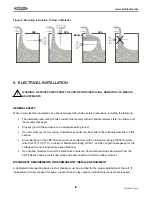
Page 9: ...ED VERTICALLY THOUGH THE TOP OF A VESSEL NEVER ATTEMPT TO MOUNT THROUGH A FULL COUPLING MOUNTING CONSIDERATIONS The VRF II Series must be located at the position where level indication is desired The probes may be mounted through the top or side wall of the vessel To ensure reliable operation observe the following guidelines when choosing the mounting location Figure 1 Mounting Orientation Do not ...

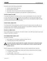
Page 10: ...s should only be made to the terminals described in this section All connections to the VRF II Series must use conductors with an insulation rating of 300V minimum rated for 212º F 105º C a minimum flammability rating of VW 1 and be of appropriate gauge for the voltage and current required see specifications Do not allow moisture to enter the electronics enclosure Conduit should slope downward fro...

Page 11: ...n only one conduit opening is used for installation the unused opening must be sealed with a suitable type 4X IP66 plug with pipe sealant in order to maintain approval requirements ELECTRICAL CONNECTIONS Note The VRF II Series can be operated from 120 240 VAC 50 60 Hz or 24 48 VDC and provides reverse polarity protection in the event of a wiring error VRF II Series INTEGRAL MODEL ONLY Input Power ...

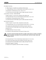
Page 12: ...leads to terminal block as shown in Figure 5 14 Check that all wires are held tightly in place by lightly pulling each conductor 15 Reinstall the gasket if necessary 16 Replace cover and tighten screws to 60 in lb 6 8 n m of torque VRF II Series REMOTE MODEL ONLY Input Power Connections 1 Refer to Figures 3 or 4 and 5 when connecting input power to the unit 2 Loosen set screw that locks cover in p...

Page 13: ...8 or 9 and 10 when connecting the remote probe 17 Pull approximately 2 5 6 cm of cable through conduit and strip 3 16 4 to 5 mm 18 Connect factory supplied cable to terminals block as shown in Figure 10 19 Check that all wires are held tightly in place by lightly pulling each conductor 20 Replace cover 21 Tighten set screw to lock cover in place 22 Loosen the remote probe housing cover screws and ...

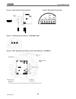
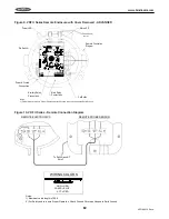
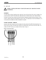
Page 14: ...ty and to insure Proper Operation Attach Ground Wire to an Adequate Earth Ground To Earth Ground Note 1 Figure 4 VRF II Series Integral Enclosure with Cover Removed ADVANCED Main Relay Connections Power Ground Connections Auxillary Relay Connections Dip Switch Power LED Alarm LED Cal Button To Earth Ground Note 1 Notes 1 For Safety and to insure Proper Operation Attach Ground Wire to an Adequate E...

Page 15: ...IMARY GROUND Figure 7 Auxiliary Relay Connections ADVANCED ONLY Figure 8 VRF II Series Remote Enclosure with Cover Removed STANDARD Power Ground Connections Dip Switch SW1 Remote Connection Diagram Main Relay Connections Notes 1 For Safety and to insure Proper Operation Attach Ground Wire to an Adequate Earth Ground To Earth Ground Note 1 ...

Page 16: ...ns Cal Button To Earth Ground Note 1 Notes 1 For Safety and to insure Proper Operation Attach Ground Wire to an Adequate Earth Ground Figure 10 VRF II Series Remote Connection Diagram GND GUARD ACT GRN BLUE RED WIRING COLORS Remote Connection Diagram REMOTE ELECTRONICS REMOTE PROBE SENSOR To Earth Ground Note 2 Notes 1 Maximum cable length is 100ft 2 For Safety and to insure Proper Operation Attac...

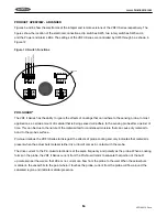
Page 17: ...D is determined by the selected fail safe mode and whether or not the probe is in material Refer to Fail Safe Operation section If the unit is calibrated prior to its final installation or if it is moved from one installation to another recalibration is required PRODUCT OVERVIEW standard Figures 3 and 8 show the electronics of the integral and remote versions of the VRF II Series respectively The ...

Page 18: ...er a period of time This can be due to the nature of the material itself or condensed moisture that can cause dry material to bond to the probe s surface Pro Guard allows the VRF II Series to disregard the effects of probe coating and only indicates that material is present when the actual bulk material either dry or liquid comes in contact with the probe The drive current to the Pro Guard electro...

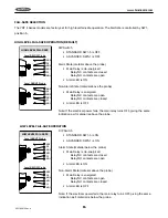
Page 19: ...ized Relay NC contacts are open Relay NO contacts are closed Alarm LED is off Note If the electrical power fails the main relay turns OFF giving the same indication as if material is above the probe LOW LEVEL FAIL SAFE OPERATION LOW LEVEL FAIL SAFE NC2 C2 NO2 NC1 C1 NO1 Level ABOVE Probe NC2 C2 NO2 NC1 C1 NO1 Level BELOW Probe DIP Switch Standard SW1 5 is On ADVANCED SW5 1 is On Alarm State materi...

Page 20: ...sing SW5 positions 2 3 The delay can be in either or both directions regardless of the fail safe setting Duration of the delay is determined by SW4 and SW5 position 5 The functionality of each switch is shown in the tables below SW5 Position 2 Delay Mode ON The selected delay by the SW4 is applied when material touches the probe OFF There is no delay when material touches the probe SW5 Position 3 ...

Page 21: ...During calibration the green POWER and red ALARM LEDs will turn on and off alternatively After a few seconds the green POWER LED illuminates to indicate calibration is successfully completed The state of red ALARM LED after calibration depends on the Fail Safe switch setting If automatic calibration recalibration is not desired set the SW1 switch position 6 to OFF Note Conductive or excessive mate...

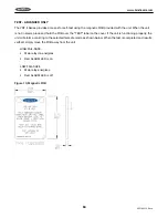
Page 22: ...ce and hold the FOB over the TEST label on the cover If the unit is functioning properly the unit will alarm according to the selected fail safe mode as shown below When the test is completed and results verified simply move the FOB away from the unit High fail safe Main relay de energizes Red ALARM LED is on Low fail safe Main relay energizes Red ALARM LED is off Figure 13 Magnetic FOB ...

Page 23: ...t is recommended to replace the gasket to prevent the ingress of water or dust At a minimum the gasket should be inspected for folds cracks and tear VIII Troubleshooting SYMPTOM POSSIBLE CAUSE SOLUTION Auxillary Relay is De energized Main relay is de energized Supply voltage is not within manufacturer recommended range Connect unit to recommended power supply and recheck both relays operations Mai...

Page 24: ...20 VRF180913 Rev A www bindicator com 20 IX DIMENSIONAL DRAWINGS venture ...

Page 25: ...21 www bindicator com VRF180913 Rev A 21 ...

Page 26: ...22 VRF180913 Rev A www bindicator com 22 venture ...

Page 27: ...23 www bindicator com VRF180913 Rev A 23 ...

Page 28: ...24 VRF180913 Rev A www bindicator com 24 Optional Lights venture ...

Page 29: ...25 www bindicator com VRF180913 Rev A 25 Optional Lights ...

Page 30: ...26 VRF180913 Rev A www bindicator com 26 Notes ...

Page 31: ...27 www bindicator com VRF180913 Rev A 27 Notes ...

Page 32: ...150 Venture Boulevard Spartanburg SC 29306 Tel 800 778 9242 Fax 864 574 8063 sales bindicator com www bindicator com 2013 All rights reserved All data subject to change without notice VRF180913 Rev A ...

Reviews: