background image

                       BC26 HYDRO-DRIVE Operator’s Manual


Part No 501530 

501530_B_HI 

MAINTENANCE 


PERIODIC


MAINTENANCE 

Periodic maintenance should be performed at the following intervals:


Maintenance Operation 

Every 

Use 

Daily or Every 

5 Hours 

Every 25 

Hours 

Every 50 

Hours 

Every 100-150 

Hours 

Inspect for worn or damaged parts 


Check for excessive vibration 


Inspect for loose parts 


Sharpen blade. Note: nut will need to be 

replaced when blade  is removed 


Inspect belts for wear 


Lubricate throttle control cable and linkage 


Check blade clutch cable tension 


Inspect battery for corrosion, damage or 

leaks (electric start units only) 


Apply anti-seize compound to rear axles 


Check battery strap for excessive wear or rips 


Replace blade drive and transaxle drive belts 


If transmission is topped off or refilled, SAE 10w30 grade, non-detergent oil should be poured through the port covered by the 

black cap. Approx. 2.2 liters of oil will be needed to reach this level. This is dependent on the amount of residual oil remaining 

in case after draining. Draining of old oil must be done through the same port (covered  with the black plug) by inverting 

transaxle 


COMMON REPLACEMENT PARTS 


  Blade. P/N 501224. Original equipment replacement blade.  

  Transaxle Drive Belt. P/N 501268. Original equipment replacement drive belt. 

  Blade Drive Belt. P/N 501220. Original equipment replacement drive belt. 

  Skid. P/N 501407. Side deck skid. 

  Throttle Control Assembly. Throttle control including cable.


CLEANING


Your BILLY GOAT

®

 Brush Cutter should be cleaned periodically to ensure optimum performance and service life. Clogs and 

debris should be removed from the blade area and debris should be removed from the engine cooling fins. A garden hose or 

pressure washer may be used for cleaning. 


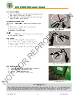
DO NOT  SPRAY WATER DIRECTLY  ON THE BLADE CLUTCH  WHEN USING A POWER 

WASHER. SEE FIG. 8.


Fig. 8 

NOT 

FOR 

REPRODUCTION

Summary of Contents for BC2601 Series

Page 1: ...art No 501530 1 501530_B_HI BC2601 Hydro Drive Series Brush Cutter Operator s Manual Beginning Serial 122020001 Original Instructions IMPORTANT READ CAREFULLY BEFORE USE AND KEEP FOR FUTURE REFERENCE...

Page 2: ...BLY INSTRUCTIONS 5 6 OPERATION 7 8 MAINTENANCE AND BATTERY MAINTENANCE 10 13 TROUBLESHOOTING 14 ILLUSTRATED PARTS LIST 15 22 Go to http www billygoat com for French Canadian translations of the produc...

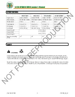
Page 3: ...lb 152 kg Overall Length 72 in 1 83 m 31 in 0 78 m 48 in 1 21 m Overall Width Overall Height Maximum Operating Slope 20 o 20 o 20 o 20 o SAFETY WARNING This product can expose you to chemicals includi...

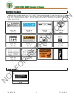
Page 4: ...ers from the Illustrated Parts List and part numbers are provided for convenience in ordering replacement labels The correct position for each label may be determined by referring to the Figure and It...

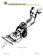
Page 5: ...BC26 HYDRO DRIVE Operator s Manual Part No 501530 5 501530_B_HI Brush Cutter Assembly Drawing N O T F O R R E P R O D U C T I O N...

Page 6: ...he hardware items 83 and 84 Tighten securely and make sure the cable isn t binding FOR ELECTRIC START MODELS Attach the throttle to the bracket then remove the starter switch item 144 from the parts b...

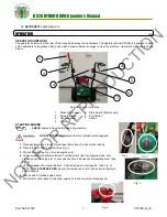
Page 7: ...hine DO NOT START equipment with drive or blade clutch engaged Fig 1 1 Place equipment on a level firm surface that is free of rocks or other debris 2 Place throttle in fast position See Fig 1 3 Pull...

Page 8: ...ft Handle Fig 6 Right Handle CUTTING OPERATION 1 Press blade clutch handle down See Fig 5 to engage blade Allow blade to spin up to normal operating speed 2 Pull Forward See Fig 6 or Reverse Drive lev...

Page 9: ...oured through the port covered by the black cap Approx 2 2 liters of oil will be needed to reach this level This is dependent on the amount of residual oil remaining in case after draining Draining of...

Page 10: ...four screws item 27 holding belt deck cover item 29 and remove the cover 3 Examine condition of belt and amount of tension on belt 4 If the idler is not providing enough tension inspect the spring ite...

Page 11: ...transaxle pulley 6 Replace the belt in reverse order NOTE make sure the belt is seated properly in the clutch and transaxle and make sure that it does not bend over the fan blades on the transaxle Fig...

Page 12: ...TER SOLENOID ENGINE GROUND M G L S WHITE RED SWITCH 1 Disconnect spark plug wire 2 Adjustments to cable tension are made at the barrel entering the Drive Control Levers See Fig 13 3 Adjust cable tensi...

Page 13: ...e Battery Operate the engine for at least 45 minutes to maintain proper battery charge If the battery loses its charge you will need to use a trickle charger to recharge it Caution The charger should...

Page 14: ...ck Excessive debris built up on or blocking blade Clear debris from blade area Engine RPM set too low Check engine RPM Abnormal vibrations Blade loose or out of balance Check blade for tightness Rebal...

Page 15: ...HYDRO DRIVE Operator s Manual Part No 501530 15 501530_B_HI BC26 HYDRO DRIVE DECK PARTS DRAWING Note Item No 169 includes Item No 44 Item No 20 Billy Goat Part No 501101 N O T F O R R E P R O D U C T...

Page 16: ...430303 1 430303 1 430303 1 29 COVER BELT DECK WA BC26 W LABEL 501602 1 501602 1 501602 1 501602 1 30 PIN COTTER 1 8 X 1 8197031 1 8197031 1 8197031 1 8197031 1 31 WASHER 765 ID X 1 25 OD X 06 THK 8502...

Page 17: ...BC26 HYDRO DRIVE Operator s Manual Part No 501530 17 501530_B_HI BC26 HYDRO DRIVE ENGINE PARTS DRAWING N O T F O R R E P R O D U C T I O N...

Page 18: ...UT1 DAXB 501361 1 501361 1 59 SCREWCAP 5 16 18 X 1 3 4 HCS ZP 8041031 2 8041031 2 8041031 2 8041031 2 SCREWCAP 1 4 28 X 1 2 HCS GR5 ZP 60 WASHER 5 16 FLAT 8171003 4 8171003 4 8171003 4 8171003 4 61 LA...

Page 19: ...BC26 HYDRO DRIVE Operator s Manual Part No 501530 19 501530_B_HI BC26 HYDRO DRIVE HANDLE PARTS DRAWING N O T F O R R E P R O D U C T I O N...

Page 20: ...2 1 501502 1 501502 1 501502 1 86 PLUG TUBE INSERT 1 25 OD 791056 4 791056 4 791056 4 791056 4 87 GRIP HANDLE 500267 2 500267 2 500267 2 500267 2 88 GUARD HAND BC26 501215 2 501215 2 501215 2 501215 2...

Page 21: ...6 _ I ____ 1 t l 1 I I 11 3 1 106 C_ 01 4 I I 28 l 79 I _ I I I 7 I I BC26 HYDRO DRIVE Operator s Manual Part No 501530 21 501530_B_HI BC26 HYDRO DRIVE TRANS PARTS DRAWING N O T F O R R E P R O D U C...

Page 22: ...O DR 351347 2 351347 2 351347 2 351347 2 103 SPACER EYELET SPEED CONTROL 351348 2 351348 2 351348 2 351348 2 104 BUSHING 3 8 ID 1 2 OD X 3 8 LONG 840078 4 840078 4 840078 4 840078 4 105 BUSHING 500 I...

Page 23: ...NG IDLER BC 501261 1 501261 1 501261 1 501261 1 161 SPRING PIN CONTROL ROD 501262 1 501262 1 501262 1 501262 1 162 SPHERICAL ROD END MSF 5 351278 1 351278 1 351278 1 351278 1 163 CONTROL ROD 501260 1...

Reviews: