background image

30

This devise complies with part 15 of the FCC Rules. 

Operation is subject to the following two conditions : 
(1) This device may not cause harmful interference. 
(2)  This device must accept any interference received,  

including interference that may cause undesired operation.

Summary of Contents for BF-PA01

Page 1: ... English SI 0125A 003 Bike Fitting System BF PA01 BF PS01 Service Instruction ...

Page 2: ......

Page 3: ...g the handlebar 15 Installing the saddle 16 Adjusting the saddle angle 18 Installing the pedals 19 ADJUSTMENT 20 Adjusting the belt tension 20 Adjusting the chain tension 20 Adjusting the resistance unit 21 Adjusting the air pressure of the tire 22 Adjusting the height and horizontal position 22 Adjusting the crank length 23 CONNECTION TO THE PC 24 Downloading application 24 Connection to the PC 2...

Page 4: ... your business as a local distributor For your safety please read this service instruction carefully and use the product correctly The following instructions must be observed at all times in order to prevent personal injury and physical damage to equipment and surroundings The instructions are classified according to the degree of danger or damage which may occur if the product is used incorrectly...

Page 5: ...form positioning with the adjustment handle or adjustment with the quick release lever while you are riding the position simulator Perform all operations while the wheels are stopped This is a class A product In a domestic environment this product may cause radio interference in which case the user may be required to take adequate measures Be sure to also inform users of the following This product...

Page 6: ...ning the chain with neutral detergent and lubricating it can be an effective way of extending the useful life of the chainrings and the chain Remove the AC cable from the resistance unit and the USB cable from the PC during installation maintenance and cleaning Products are not guaranteed against natural wear and deterioration from normal use and aging For maximum performance we highly recommend S...

Page 7: ...aling analyzer Measures the load on the pedals and outputs it to the PC C Resistance unit Applies a load on the wheel D XY position tool Measures the position of the BB saddle and handlebar using lasers E USB cable Connects the pedaling analyzer to the PC F Application software Shows information sent from the pedaling analyzer ...

Page 8: ... sure all the parts listed are present Package 1 Base frame main unit accessories Shape Part name Quantity Shape Part name Quantity Bracket 2 Bolt Long M8 18 18 Pad bracket 1 Bolt Medium M6 15 2 Pad 1 Bolt Medium M8 16 4 Saddle center tool 1 Ground cable fixing bolt for the resistance unit M4 1 Handlebar center tool 1 Handlebar spacer 1 Pedal washer 2 Stem 1 Service instruction 1 Resistance unit b...

Page 9: ...ake resistance unit for Realaxiom wired version Elite No 2014016 Package 3 XY position tool Shape Part name Quantity Shape Part name Quantity XY Position tool 1 Rail 1 Bolt Medium M6 25 4 Bolt Long M6 30 2 Magnet sheet 1 Aluminium sheet 1 Service Instruction 1 ...

Page 10: ... stable flat surface Do not install the product in a place where it may fall or children may touch it This product is for indoor use only Do not use it outdoors The recommended temperature range is 0 to 40 C Use the product within the recommended temperature range 900 mm 1800 mm Assembling the main unit and base frame 1 Attach the pad bracket to the frame of the main unit Then attach the pad Nut B...

Page 11: ...unit to the base frame Fix the bolts long to the bracket with a 6 mm Allen key as shown in the illustration Then fix the four bolts short to the nuts with a 5 mm Allen key Note The main unit is heavy Approx 65 kg Be sure to assemble the product in groups of two or more Bolt Short Nut 5 mm Allen key Tightening torque 12 3 N m 108 in lbs 6 mm Allen key Bolt Long ...

Page 12: ...ue 23 5 N m 206 in lbs Bracket Bolt Long 6 mm Allen key Bracket 4 3 1 2 Wide Narrow Tighten the bolts in the order below 5 Adjust the height of the pad and level its mount Adjust the height of the five pads using the height adjustment screw and a spirit level After leveling tighten the upper fixing nut with a 19 mm spanner Fixing nut Height adjustment screw ...

Page 13: ...ts Tightening torque 12 3 N m 108 in lbs Install the stem so that the nut of the quick lever does not interfere with the position adjustment handle 5 mm Allen key WARNING Install the stem below the upper end of the support If it is installed above the upper end of the support it may cause the stem to be insufficiently fixed and lead to unexpected accidents ...

Page 14: ...the base frame with the screw holes in the bracket Fix the bracket with the bolts long using a 6 mm Allen key and lower the height adjustment mount of the resistance unit Finally fix the top fixing plate to the base frame with the four bolts medium Tightening torque 23 5 N m 206 in lbs Resistance Unit Bolt Washer 1 2 3 Attach the ground cable Remove the bolt from the resistance unit pass it throug...

Page 15: ...nstall the rail to the base frame Align the four mounting holes in the rail with the nuts on the base frame and fix it with the rail fixing bolts 2 Next peel off the seal from the back of the magnet sheet and affix the magnet to the rail 3 Then affix the aluminum sheet to the rail in the same way Tightening torque 5 1 N m 45 in lbs Rail fixing bolt 4 mm Allen key 1 2 3 25 mm M 6 ...

Page 16: ...14 4 Insert the XY position tool unit from the end of the rail 5 Then attach the bolts on both ends 5 4 30 mm M 6 Tightening torque 5 1 N m 45 in lbs 4 mm Allen key ...

Page 17: ...m can also be supported by using the handlebar spacer Quick release lever Clamp Note The stem included in the package is only for Bike fitting system Do not use it for bicycles 2 Close the clamp and set the quick release lever into the slit of the clamp Then lower the quick release lever and fix the handlebar Adjustment nut 3 If the quick release lever can be easily set to the CLOSE position it me...

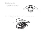
Page 18: ...en the rails 0 10 20 30 40 43 mm 1 Set the saddle so that the saddle rails are aligned with the grooves in the saddle rail mount Hook the ends of the fixing levers on the saddle rails and adjust the angle and horizontal position of the saddle Fixing lever ...

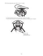
Page 19: ...e The clamp may be tightened too easily or excessively depending on the shape of the saddle rail If this is the case open the clamp and turn the adjustment screw at the bottom of the fixing lever to adjust the tightness Clockwise Tighter Counterclockwise Looser Adjustment screw ...

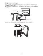
Page 20: ...lamp mount with the grooves in the saddle rail mount Adjustment can be made in 2 5 degrees increments by reversing the saddle rail mount horizontally as its grooves are arranged with different pitches Saddle rail mount Saddle clamp mount To reverse the saddle rail mount horizontally raise and turn the saddle rail mount when the clamp is opened ...

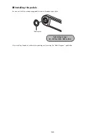
Page 21: ...Be sure to attach the accompanying pedal washer to the pedaling analyzer Pedal washer Tightening torque 35 55 N m 306 480 in lbs After installing the pedals calibrate the pedaling analyzer using the bikefitting com application ...

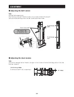
Page 22: ...from side to side to adjust the belt tension The belt becomes tighter The belt becomes looser Tightening torque 5 1 N m 45 in lbs Tension adjustment bolt Adjusting the chain tension Note Use the chain under proper tension If the chain is too tight it may put a load on the chain and chainrings and result in the chain breaking or coming off Chain tension guideline The chain can be bent 15 to 25 mm b...

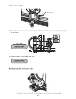
Page 23: ...tension After adjusting it tighten the four setscrews Tightening torque 5 1 N m 45 in lbs 3 mm Allen key 3 Tighten the four bolts to fix the support to the frame Tightening torque 12 3 N m 108 in lbs Adjusting the resistance unit Lower Higher For information on how to adjust the resistance setting etc refer to the service instruction provided ...

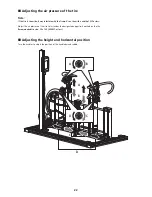
Page 24: ... a tire with a width of 32C or less Adjust the air pressure of the tire to just under the designated upper limit marked on the tire Recommended tire size 20 x 1 25 406 32C or less Adjusting the height and horizontal position Turn the handles to adjust the position of the handlebar and saddle A D A C B D B C ...

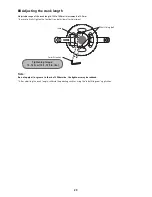
Page 25: ... tighten the four bolts on both sides after adjustment Tightening torque 14 16 N m 123 139 in lbs 5 mm Allen key Scale Shaft fixing bolt Note Do not apply oil or grease to the shaft Otherwise the tightness may be reduced After adjusting the crank length calibrate the pedaling analyzer using the bikefitting com application ...

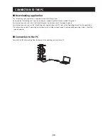
Page 26: ...how to install the bikefitting com application check the support website For information on how to use the bikefitting com application on the PC refer to the Operating Manual for the application For information on the PC operating environment such as hardware requirements and supported operating systems check the support website Connection to the PC Connect the USB cable running from the board of ...

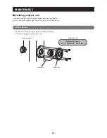
Page 27: ...ibration Contact a dealer and send the right and left cranks and the BB side coil unit Bottom bracket Use the Shimano original tool TL BB12 to perform press fitting The inner cover does not need to be used Bottom bracket Connector BB coil unit Tightening torque 0 4 0 6 N m 3 5 5 2 in lbs Screwdriver 2 ...

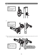
Page 28: ...ted as far as they will go 3 Tighten the bolts on both sides alternately while making sure that the cord support does not interfere with the tool Finally make sure that there is no looseness in the direction of the BB axis Note When tightening the bolts be careful not to pinch the cord Tightening torque 12 14 N m 105 122 in lbs 5 mm Allen key ...

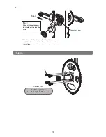
Page 29: ...the sticker so that the letters on it are readable when the crank is in the position shown in the illustration Note When attaching the cover be careful not to pinch the cord Chainring Tightening torque 16 17 N m 140 148 in lbs Hexalobular 30 Bolt ...

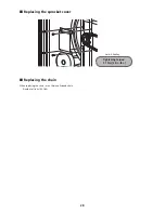
Page 30: ...28 Replacing the sprocket cover Tightening torque 5 1 N m 45 in lbs 3 mm Allen key Replacing the chain When replacing the chain use a Shimano 9 speed chain Number of links 108 links ...

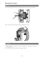
Page 31: ...otches TL BB12 TL FW45 2 Turn TL FW45 counterclockwise to remove the freewheel while holding the wheel firmly Installation 1 Rotate the freewheel clockwise by hand until it can turn no further and follow the same procedure as for removal to set TL BB12 and TL FW45 2 Turn TL FW45 clockwise to tighten the freewheel while holding the wheel firmly ...

Page 32: ...t 15 of the FCC Rules Operation is subject to the following two conditions 1 This device may not cause harmful interference 2 This device must accept any interference received including interference that may cause undesired operation ...

Page 33: ...Please note specifications are subject to change for improvement without notice English May 2015 by Shimano Inc HTR ...

Reviews: