


Turn the control knob to "OFF" position.
Turn LP cylinder to OFF position.
Allow at least 45 minutes for the fire pit to
cool down after use, then disconnect and
remove the cylinder.
Cylinder must be stored outdoors in a
well-ventilated area out of the reach of chil-
dren. When the cylinder is disconnected,
tightly install the threaded valve plugs, and
do not store it in a building, garage or any
other closed area.
You may store product indoors ONLY if the
cylinder is disconnected and removed.
Keep the fire pit area clear and free from
combustible materials, gasoline and other
flammable vapors and liquids.
Cover the fire pit with a cover.
Note: If you do not use a cover, store this
outdoor fire pit in a dry location to maximize
product life.
Store gas fire pit in an area sheltered from
direct contact with inclement weather (such
as rain, sleet, hail, snow, dust and debris).
A qualified service person should install
and repair the fire pit and inspect it annually.
It might be necessary to clean this fire pit
frequently. You must keep the control com-
partment, burner and circulating air pas-
sageways clean.
9
Cleaning and maintenance
To enjoy years of outstanding performance
from your gas fire pit make sure you perform
the following maintenance activities on a
regularbasis:
the area around the burner and
trols, burner, and circulating air passage-
include:
Appliance does NOT reach the desired tem-
Clean burner holes by using a heavy-duty
GB
least once per month and each time the
cracking, splitting or other deterioration, it
STORAGE
Between uses:
Keep the appliance area free and clean
from combustible materials, gasoline and
other flammable vapors and liquids; not
obstructing the flow of combustion and
ventilation air; keeping the ventilation
opening(s) of the cylinder enclosure free and
clear from debris.
Summary of Contents for SRGF11626
Page 11: ...11 EXPLODED VIEW GB F L A G H I K E B D C M J ...
Page 13: ...ASSEMBLY INSTRUCTIONS 13 1 GB 2 AA x 4 M5 x 12 A AA C M METAL TUBE ELECTRODE GAS HOSE WIRE ...
Page 14: ...14 4 BB x 6 M5 x 12 BB ASSEMBLY INSTRUCTIONS GB B G H 3 DD DD x 12 M6 x 12 H A E D G ...
Page 15: ...15 6 BB x 6 M5 x 12 BB ASSEMBLY INSTRUCTIONS GB D E B 5 BB D G BB x 6 M5 x 12 B ...
Page 16: ...16 8 ASSEMBLY INSTRUCTIONS GB I J 7 CC x 4 M5 x 20 CC E K H G D ...
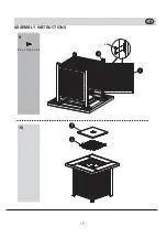
Page 17: ...17 10 ASSEMBLY INSTRUCTIONS GB F L 9 EE x 4 ST4 2 x 9 5 EE I H ...