background image

14

4

BB x 6  M5 x 12

BB

ASSEMBLY INSTRUCTIONS

GB

B

G

H

3

DD

DD x 12   M6 x 12

H

A

E

D

G

Summary of Contents for SRGF11626

Page 1: ...30 Slate Table top Gas Fire Pit Model No SRGF11626 Keep the instructions for future reference GB 0063 18 ...

Page 2: ...e type of gas and the type of cylinder specified by the manufac turer Warning Do not obstruct the ventilation holes of the cylinder housing Warning In case of violent wind particular attention must be taken against tilting of the appliance Warning Do not move the appliance when in operation Warning Shut off the valve at the gas cylin der or the regulator before moving the appli ance Warning The tu...

Page 3: ...T NL NO SE SI SK RO HR TR BG IS LU MT I3B P 30 15kW 1090 g h G30 1 88mm G30 Butane and G31 Propane at 30mbar BE CH CY CZ ES FR GB GR I E IT L T LU LV PT SK SI I3 28 30 37 15kW 1090 g h G30 1 88mm G30 Butane at 28 30mbar and G31 Propane at 37mbar 3 Technical data GB Manufacturer SHINERICH INDUSTRIAL LIMITED Address 8 F Noble Center 1006 Fuzhong 3rd Road Futian District Shenzhen GD 518026 CHINA ...

Page 4: ... steps in order to properly assemble your product Make sure all the plastic protection rip off before assembling Do not force parts together as this can result in personal injury or damage to the product When applicable tighten all hardware con nections by hand first once the step is com pleted go back and full tighten all hardware Caution Whilst every effort has made in manufacture of your applia...

Page 5: ...ppliances Connect LP Gas cylinder Before connecting be sure that there is no debris caught in the head of the LP tank head of the regulator valve or in the head of the burner and burner ports Connect gas line to tank by turning knob clockwise until it stops make sure that the tube is not subject to twisting After connecting to gas cylinder a leak test ing is necessary Important Notes LPG cylinder ...

Page 6: ...se regulator and regulator LPG cylinder connection 3 Inspect the connections and look for bubbles 4 If no bubbles appear the connection is safe If bubbles appear there is leak loosen and re tighten this connection Repeat the test If bubbles form again stop trying contact your local dealer for assistance Leak test annually and whenever the gas cylinder is removed or replaced Note In the event of ga...

Page 7: ...ant fibres plas tic or other materials that are capable of being ignited and burned Always make sure that adequate fresh air ventilation is provided Follow the spacing tolerances shown in the following figure right at all times This appliance must be placed on level firm ground Never operate in an explosive atmosphere Keep away from areas where gasoline or other flammable liquids or vapors are sto...

Page 8: ...erviced and or repaired by a qualified service technician Shut down instructions 1 Push in and turn control knob clockwise to OFF position 2 Turn LPG cylinder gas valve clockwise to OFF position when heater is not in use The event of gas leakage 1 Turn the control knob to OFF position 2 Turn LPG cylinder valve to OFF position 3 Wait 5 minutes to allow gas to dissipate 4 If odor continues immediate...

Page 9: ...ith inclement weather such as rain sleet hail snow dust and debris A qualified service person should install and repair the fire pit and inspect it annually It might be necessary to clean this fire pit frequently You must keep the control com partment burner and circulating air pas sageways clean 9 Cleaning and maintenance To enjoy years of outstanding performance from your gas fire pit make sure ...

Page 10: ...pressure The distance between electrode ignition pins is too far Clogged or dirty burner ports CORRECTIVE MEASURES Check all gas connections Check gas supply pressure Clean burner parts see manual CLEANING AND MAINTENANCE section Check gas supply pressure Clean burner parts Adjust the distance between the ignition pins to be 4 5mm in case of ignition failure if ignition failure issue happened 4 5m...

Page 11: ...11 EXPLODED VIEW GB F L A G H I K E B D C M J ...

Page 12: ... Front Right Leg Lid Front Left Leg Back Left Leg 1 3 1 1 1 1 1 1 B Gas Valve Panel 1 C I Door Knob 1 J Base Frame 1 K Lava Rock 1 L Regulator 1 M D E F H G Picture Qty Part Picture Qty 4 18 M5 x 12 4 12 4 M5 x 20 M6 x 12 ST4 2 x 9 5 M5 x 12 Hardware AA BB CC DD EE Picture Qty Dimensions GB ...

Page 13: ...ASSEMBLY INSTRUCTIONS 13 1 GB 2 AA x 4 M5 x 12 A AA C M METAL TUBE ELECTRODE GAS HOSE WIRE ...

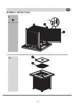
Page 14: ...14 4 BB x 6 M5 x 12 BB ASSEMBLY INSTRUCTIONS GB B G H 3 DD DD x 12 M6 x 12 H A E D G ...

Page 15: ...15 6 BB x 6 M5 x 12 BB ASSEMBLY INSTRUCTIONS GB D E B 5 BB D G BB x 6 M5 x 12 B ...

Page 16: ...16 8 ASSEMBLY INSTRUCTIONS GB I J 7 CC x 4 M5 x 20 CC E K H G D ...

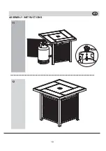
Page 17: ...17 10 ASSEMBLY INSTRUCTIONS GB F L 9 EE x 4 ST4 2 x 9 5 EE I H ...

Page 18: ...12 18 ASSEMBLY INSTRUCTIONS GB 11 ...

Reviews: