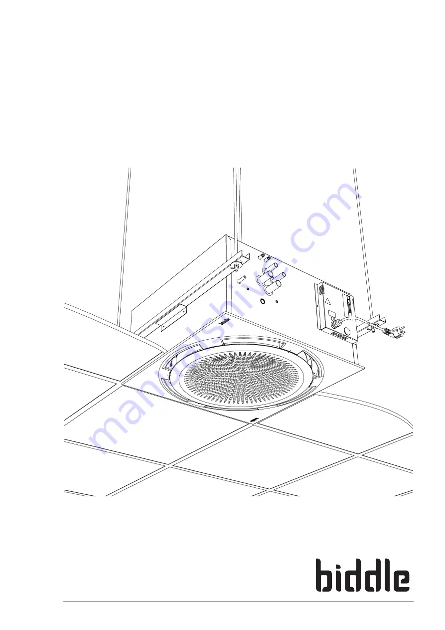
Manual
Cassette Air Heater/Cooler
Model Comfort Circle
a
Version of Guide: 1.0
R
Page 1: ...Manual Cassette Air Heater Cooler Model Comfort Circle a Version of Guide 1 0 R...
Page 2: ...description of the relevant parts Biddle disclaims all liability for damage resulting from any inaccuracies and or deficiencies in this manual Should you detect any errors or ambiguities in this manua...
Page 3: ...ional discharge connection 20 2 10 Connecting the unit to the power supply 21 2 11 Mounting the cover 21 2 12 Adjusting the discharge pattern 22 2 13 Installing the controller 23 2 14 Connecting the v...
Page 4: ...the installer 46 7 4 Fault messages in the controller 49 8 Service 52 8 1 Safety instructions 52 8 2 Service menu 52 8 3 Resetting and reconfiguring the controller 52 8 4 Accessing the interior of the...
Page 5: ...mages So read this manual carefully before starting to handle the unit in any way 1 2 How to use this manual If you are unfamiliar with the Comfort Circle read this man ual section by section If you a...
Page 6: ...r repair works 1 2 2 Icons used on the unit and in the manual The icons in Table 1 1 warn against potential risks or dangers The icons can be found opposite text discussing risk entailing operations T...
Page 7: ...Circle blows out a flow of heated or cooled air creating a comfortable climate in the room The units that can both heat and cool have automatic dis charge angle control which determines the discharge...
Page 8: ...load on the electrical system Table 1 2 Type code explained TYPE CODE ELEMENT REFERENCE MEANING product series Comfort Circle general reference for the Comfort Circle physical size 60 or 90 dimensions...
Page 9: ...llowing components are delivered separately but are always required controller 7 control cable 8 available in various lengths Accessories The following accessories are available as options low limit s...
Page 10: ...maintenance and service Danger d The unit may be opened by qualified technical staff only Warning w Before opening the unit do the following 1 Switch the unit off using the controller 2 Wait until the...
Page 11: ...onents have been delivered see section 1 3 5 Immediately report any defects to the sup plier 2 3 General working method Order of working Biddle recommends the following working method for install ing...
Page 12: ...for protection 2 4 Mounting the unit 2 4 1 Positioning the unit Make sure that the structure from which the unit is about to be suspended can hold the weight of the unit The weight is specified on th...
Page 13: ...les 4 You can still change the position of the unit somewhat by moving it in the suspension profiles and Flamco rails 5 Secure the suspension on both sides using the securing brackets 4 6 Bring the un...
Page 14: ...eters of the compression fittings per unit type Warning w Prevent the pipes from twisting Caution c Biddle recommends to include close to the unit a shut off valve and a relief valve in both pipes The...
Page 15: ...ector 2 according to the wiring diagram 3 Fill and bleed the system 4 Check the connections for leaks 2 6 Connecting change over 2 6 1 Introduction If a unit is integrated into a change over system th...
Page 16: ...e of the system 2 6 3 Signal to the unit s input If contact is made to the unit s input the unit will switch from heating mode to cooling mode see table 3 1 function 90 1 Connect the signal cable to t...
Page 17: ...O1 function to value 57 3 Set function 91 5 to value 0 make contact If the unit switches from heating mode to cooling mode a signal is sent to the output 2 7 Connecting the condensate discharge CC C...
Page 18: ...prevent draught when the unit is switched off Biddle recommends to include air valves 2 in the air intake ducts 1 Connect insulated ducts with a diameter according to table 2 3 to the unit 2 Connect t...
Page 19: ...to output O3 For ventilation units the function of output O3 is set to the default value 70 with contact being made to the output when the fans are rotating If the discharge temperature falls below 6...
Page 20: ...Cut the connections of the prepunched hole 2 2 Cut the insulation material Caution c In doing so do not damage the heat exchanger 3 Press the saddle piece 3 onto the hole 4 Mount the ductwork and the...
Page 21: ...eat the angle adjustment ring is driven by a servomotor In the other units the position of this ring is fixed In heating and ventilating units the ring is in a high posi tion In cooling units the ring...
Page 22: ...c If use is made of the air connection for an adjoining room the two blind plates must be mounted in the two holes on the side of this connection Caution c Do not mount more than two blind plates per...
Page 23: ...es from Biddle Biddle Standard mod ular telephone cable is not suitable Multiple units operated from one controller Up to 10 units can be connected to one single controller To do so the units must be...
Page 24: ...upper left pull relief 2 is designed for the control cable and the upper right pull relief 3 for the external control cable The cable must protrude some 9cm from the pull relief 7 Couple the connecto...
Page 25: ...and the corresponding tapped trans former are not included in the ventilation module deliv ered Caution c Do not connect any ventilation module other than the VM CC to the CC V 1 Install the ventilat...
Page 26: ...limit or room thermostat or a BMS signal may be con nected The effect of the input signal depends on the controller set tings see section 4 2 3 A signal to one unit will have the same effect on all un...
Page 27: ...n setting The 0 10VDC output can for instance be used for control ling an extraction fan 2 15 6 Options and operation Options and operation depend on the in or output as well as on the controller sett...
Page 28: ...sure the CH and CW systems are switched on 4 Switch the mains power on and or plug in all connected units If you switch on the mains power for the first time the dis play will briefly show the number...
Page 29: ...some time You may want to read the actual discharge tem perature from the service menu section 8 2 only for CC M parameters 36 and 37 9 Only units that can both heat and cool Check if the position of...
Page 30: ...ice purposes 4 In the service menu you can read information on the opera tion of the unit see section 8 This section deals with the installation menu The access to the installation menu and the timer...
Page 31: ...on menu To go to the next function press the key To go to the previous function press the key To change the value of the function press or To default the value press and simultaneously To return to th...
Page 32: ...he AUTO mode CC M Can be set between 1 and 5 C 1 5 C 61 Dead band around temperature setpoint for heating CC S Can be set between 0 5 and 4 C 0 8 C 62 Dead band around temperature setpoint for cooling...
Page 33: ...99 50 85 0 10VDC output This output can be used for instance to con trol an extraction fan or an air valve 0 not enabled 1 enabled 86 Output voltage at fan speed 1 0 99 on 40 in tenths of volts 87 Out...
Page 34: ...input has a global effect a signal to one unit has the same effect in all units connected to the control ler 3 3 2 Particulars of the outputs The functions 91 92 and 93 allow you to choose the func ti...
Page 35: ...e input the unit s temperature control is switched off The and keys will have no function anymore when they are pressed __ appears in the display The fan speed can still be regulated and can be used i...
Page 36: ...on and ventilation units which provide indi vidual ventilation control 4 1 Switching on and off 4 1 1 Switching the unit on and off You can switch the Comfort Circle on and off manually Inde pendently...
Page 37: ...ature 22U To set the desired room temperature press or The unit will try to reach the desired temperature The fan of units with simple control switches off when the desired tem perature is reached The...
Page 38: ...on volume press the key You can choose from 4 ventilation volume settings ventilating at speed 1 2 or 3 The ventilation units will run at low medium or high fan speed The arrows indicate the speed rec...
Page 39: ...operates as a heating device The symbol indicates that the unit operates as a cooling device 4 6 3 External controls The symbol in the display indicates that the Comfort Circle is switched on or off...
Page 40: ...isplayed refer to section 7 4 and if necessary alert the installer or other expert Note n The fault code will disappear when you press a key The message S will however remain visible as long as the fa...
Page 41: ...l keep on running when there is a power outage The battery has a minimum life of 10 years When its life has lapsed the day and time will have to be entered again after a power out age 5 1 Setting the...
Page 42: ...er or use an external timer 1 use the timer in the controller 5 To go to the next setting press the key The control ler now displays d1 0 as well as the symbol This is the starting time on Monday 6 Se...
Page 43: ...ad to inadequate heating as well as a high noise level The interval at which the filter is to be cleaned depends on the local condi tions The Comfort Circle is designed such that the filter can stay i...
Page 44: ...r d This may be carried out by qualified staff only 1 Switch the unit off 2 Disconnect power supply remove plug from socket or move main switch to Off 3 Remove the air inlet grille 4 Loosen screw 1 bu...
Page 45: ...of the fans Clean the unit s drip tray for removing the drip tray see section 8 4 1 Remove the filter from the condensate pump see section 6 4 6 4 Cleaning the condensate pump filter Warning w This m...
Page 46: ...le 7 1 You need not be an expert for this 7 3 Fault finding by the installer If table 7 1 does not provide the solution to the problem table 7 2 can be used to investigate the fault further If a fault...
Page 47: ...press and simultaneously If the display shows the clock symbol or the arrows symbol the unit is controlled by an external control This is not a fault Operation is limited by the input signal from the...
Page 48: ...onnections the wiring and the fuse of the electronics module The connection between the controller and the unit is not correct Check the control cable The PCB does not work 1 Check the feeder cable 2...
Page 49: ...No technical expertise is needed for this No longer current faults If a fault occurred in your absence but has been automatically cleared in the meantime only the fault code is displayed It will disap...
Page 50: ...section 2 5 2 Freezing may cause damage to the heat exchanger 1 Ensure that the temperature in the room gets higher than 8 C 2 Check the operation of the CH system 3 Check the discharge temperature se...
Page 51: ...ace the sensor F7 The change over sensor does not work 1 Check the sensor s wiring and connection con nector X360 2 Replace the sensor F8 Fault at 0 10VDC input voltage exceeds 10 V voltage is 0 V 1 C...
Page 52: ...he key and the key simultaneously To browse through the menu press the key To exit the menu press the key 8 3 Resetting and reconfiguring the controller In some situations it may be necessary to reset...
Page 53: ...irst the number along with the fault code 1 and then the time 2 in hours lapsed since the occur rence appear in the display 24 25 26 27 28 Number of units connected to the controller 29 Input voltage...
Page 54: ...tion c The drip tray may still contain some water Warning w The heat exchanger can be hot 8 4 2 Ventilation units 1 Switch the unit off using the controller Warning w Disconnect the power supply pull...
Page 55: ...the PCB 1 the transformer 2 the fan capacitor 3 the fuse 4 If necessary the connections of fan condensate pump angle adjustment motor and temperature sensors can be accessed via the bottom of the uni...
Page 56: ...ove isolation switch to Off 2 Remove the screws 1 from the electronics module 2 3 Take out the electronics module 2 4 Disconnect all unit connected connectors and earth con nections from the electroni...
Page 57: ...tion units Remove the main cover see section 8 5 2 Open the drain plug 1 of collector 2 The CC H1 C2 has two drains Caution c After refilling the system check the sealing of the drain plug 8 10 Settin...
Page 58: ...number press the key 9 Repeat the previous two steps until you entered all four numbers No number will be blinking any more 10 Store the unit code by pressing the key The unit code has now been set I...
Page 59: ...MANUAL Version 1 0 21 09 2005 59 This page is intentionally blank...
Page 60: ...cker EN 61000 6 3 2001 Emission IEC 61000 4 2 2001 Immunity electrostatic discharge IEC 61000 4 3 2002 Immunity electromagnetic field IEC 61000 4 8 2001 Immunity 50 Hz Magnetic field IEC 61000 4 4 200...