UPS-1000-B1
Revision 1
13
F General Data
F1 Assembly and installation advice
Installation and operation of this device is only allowed to be executed by a qualified
electrician!
The application has to be separated from any power during the mounting process.
Wires have to be connected safely and must not have contact with sharp edges. Before com-
missioning, check all the connections for correctness!
Please check the shipping box for any transport damage immediately upon receipt. If you have any problems,
please contact your forwarding agent or parcel service. Please always send the UPS in the original box .
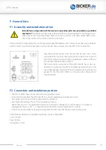
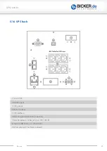
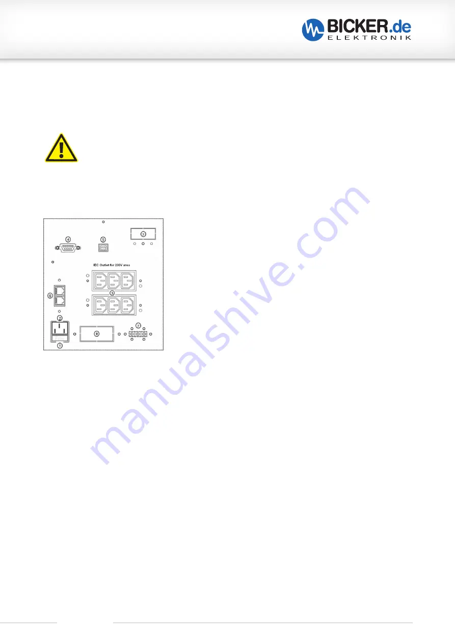
Plug the enclosed power cord into the UPS (2) and into a 3-pin
socket (with PE). Connect the load (e.g. PC) to the mains output of
the UPS (3). Plug the enclosed USB or green RS232 cable to USB and
PC and install UPSilon2000 on the PC.
The 3-pole mains connection of the UPS-1000-B1 has to be con-
nected to a 3-pole circuit (with PE / earth) protected with 16 A. The
sum of the leakage currents (UPS and connected devices) must not
exceed 3.5 mA. The UPS-1000-B1 can be live even in the event of
a power failure!
F2 Convection and installation position
• The UPS-1000-B1 may only be installed in an upright position.
• It must be ensured that the UPS-1000-B1 may bot be loaded beyond maximum load.
• This value can be found in the technical data in chapter A.
• Also mind the derating. This is to be calculated as follows:
600 W load at +40 °C. The permitted load to be connected is reduced by 10 W for every 1 K increase in
temperature. Thus, at +60 ° C, a maximum load of 400 W is permitted at the UPS output.
• It has to be ensured that no foreign matter enters the UPS and that the fan outlet is always free.
The following distances to neighboring devices are recommended:
Front: 50 mm
Back: 50 mm
Fan (right): 50 mm
Summary of Contents for UPS-1000-B1
Page 3: ...UPS 1000 B1 Revision 1 3...

