background image

42

English

UPSI-IP-1 series | UPSI- IP-2 series

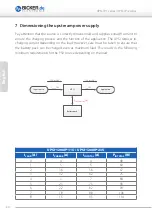
UPSI-2406IP-26UW

I

LOAD

 [A]

I

CHARGE

 [A]

I

LOAD

 [A]

P

LOAD

 [W]

P

IN TOTAL

 [W]

0

3

3

72

80

1

3

4

96

107

2

2.7

4.7

113

126

3

2.5

5.5

132

147

4

2.2

6.2

149

165

4.6

2.15

6.75

162

175

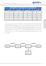
UPSI-2406IP-24UW

I

LOAD

 [A]

I

CHARGE

 [A]

I

LOAD

 [A]

P

LOAD

 [W]

P

IN TOTAL

 [W]

0

3

3

72

80

1

3

4

96

107

2

2.7

4.7

113

126

3

2.5

5.5

132

147

4

2.2

6.2

149

165

5

2

7

168

171

5.42

1.4

7.4

178

187

UPSI-1208IP-23UW

I

LOAD

 [A]

I

CHARGE

 [A]

I

LOAD

 [A]

P

LOAD

 [W]

P

IN TOTAL

 [W]

0

4

4

48

52

1

5

5

60

66

2

3.6

5.6

67

74

3

3.2

6.2

75

82,5

4

3

7

84

92,5

5

2.5

7.5

90

100

6

2.2

8.2

99

110 

7

1.8

8.8

106

127

8

1.5

9.5

114

127

Summary of Contents for UPSI-1208IP-11U

Page 1: ...Deutsch English Benutzerhandbuch User Manual UPSI IP 1 series UPSI IP 2 series...

Page 2: ...UPSI IP 1 Serie UPSI IP 2 Serie 2 Deutsch UPSI IP 1 UPSI IP 2...

Page 3: ...7 Dimensionierung der vorgeschalteten Stromversorgung 10 8 Inbetriebnahme 13 9 Anschlussplan 14 10 Sicherheitsma nahmen 15 11 Ladezeit 15 12 Verpolung berlast Kurzschluss bertemperatur 16 13 berbr ck...

Page 4: ...Sie basieren auf den Technologien der UPSI 1208 2406 Bei den unterschiedlichen Speichermedien nachfolgend auch Batteriepack Akku etc handelt es sich entweder um Supercap oder LiFePO4 Packs Zudem verf...

Page 5: ...on oder das Herunterfahren eines Systems Als Speichermedien wel che neben der USV Platine ebenso im Produktgeh use montiert sind dienen hierbei jeweils in Reihe und oder parallel geschaltete Superkond...

Page 6: ...x 232 x 110 mm UPSI 1208IP 23UW 7 36 V DC Normal 11 5 V DC Backup 12 V DC 8 A 96 W max BP SUC 10066 IP 2 Typ 202 x 232 x 110 mm UPSI 2406IP 24U 24 V DC Normal V in 1 V Full load Backup 23 5 V DC 6 A...

Page 7: ...e waagrechte Montage ber Kopf ist jedoch aufgrund von schweren Komponenten im Boden des Geh uses nicht empfehlenswert Grunds tzlich k nnen die Ger te ohne fremde Luftzirkulation betrieben werden Das b...

Page 8: ...or 09 4224 00 04 USB interface connector case side Snap in flange socket 5 poles Binder Connector 99 9116 00 05 DC counter connector 1 cable side RD24 cable socket poles 3 PE Binder Connector 99 0210...

Page 9: ...nector 99 9116 00 05 DC counter connector 1 cable side RD24 cable socket poles 3 PE Binder Connector 99 0210 00 04 DC counter connector 2 cable side RD24 cable plug poles 3 PE Binder Connector 99 0209...

Page 10: ...h Last den Ladestrom Es muss jedoch daf r gesorgt werden dass auch bei h herer Last geladen wird Daraus ergeben sich folgende Mindestanforderungen an die Quelle in Abh ngigkeit von der Last 12 V or 24...

Page 11: ...schaltet sodass hier Eingangsstrom IIN nicht pauschal angegeben werden kann Die Eingangsspannung variiert zwischen 7 bzw 8 und 36 V in Abh ngigkeit dazu ver ndert sich hier der Eingangsstrom Hinzu kom...

Page 12: ...2 175 UPSI 2406IP 24UW ILOAD A ICHARGE A ICHARGE LOAD A PCHARGE LOAD W PIN TOTAL W 0 3 3 72 80 1 3 4 96 107 2 2 7 4 7 113 126 3 2 5 5 5 132 147 4 2 2 6 2 149 165 5 2 7 168 171 5 42 1 4 7 4 178 187 UPS...

Page 13: ...ith long lines up to 3m in length up to 1 V and more can fall over these lines Es muss an der Quelle stets eine ausreichende Spannung eingestellt sein um diesen Abfall auszugleichen Auch wirkt sich de...

Page 14: ...G FG VOUT VOUT Erdnocken im Geh use UPSI 1208 2406 Bateriepack BP LFP 1025 oder BP LFP 1325 oder BP SUC 10066 oder BP SUC 16090 oder BP LFP 1375 4 LiFePO4 oder 5 EDLC BAT DATA Anschlussplan UPSI 1208I...

Page 15: ...H R 50 m kann ein Schutz gew hr leistet werden Warnung Missachtung nachfolgender Punkte kann einen elektrischen Schlag Br nde schwere Unf lle oder Tod zur Folge haben 1 Die Eingangsspannung muss vor I...

Page 16: ...ratur am Sensor unterhalb des Schwellwertes sinkt 13 berbr ckungszeiten Die nominalen berbr ckungszeiten k nnen den Datenbl ttern entnommen werden Die Energiespeicher weisen unterschiedliche Eigenscha...

Page 17: ...unterfahren Warten bis System herunter gefahren ist 4 x blinken Pause 1 5s Status Neustart Ausgang ist abgeschaltet und Zeit l uft bis Neustart Rebootphase 5 x blinken Pause 1 5s Status Keine Batterie...

Page 18: ...ku sollte immer eine gr ere Kapazit t als tats chlich ben tigt verwendet werden Je weni ger tief die Packs entladen werden desto h her ist die Lebensdauer 17 Wartung Die USV enth lt keine zu wartenden...

Page 19: ...zus tzliche Software ben tigt und kann dadurch mit den internen Akku Einstellungen des Betriebssystems gesteuert werden Falls ein Herunterfahren nach Zeit gew nscht ist kann mit der Software UPSI HID...

Page 20: ...gsspannung wird nur im Normalbetrieb angezeigt Output Voltage Ausgangsspannung wird immer angezeigt Output Current Strom der Applikation Battery Voltage Spannung am Akkupack Battery Current Strom am A...

Page 21: ...Eingang wiederkehrt wird nichts unternommen Maximum Backup Time 1s 3600s in s schritten Die maximale berbr ckungszeit Nach dieser Zeit wird das System getrennt Diese Einstellung kann eingesetzt werde...

Page 22: ...eset Parameter werden die Einstellungen auf die Standardwerte zur ckgesetzt Speichern der Parameter Mit Save werden die Einstellungen auf der USV gespeichert Die Software kann dann geschlossen werden...

Page 23: ...Type Min Max Unit 0x62 GetDeviceName R char Transfer packet 0x01 0x03 0x01 0x62 0x04 GetFirmwareVersion 0x63 This read function returns the firmware version as string Cmd Name Access Type Min Max Uni...

Page 24: ...nit 0x01 GetOutputCurrent R Int32 0 32768 mA Transfer packet 0x01 0x03 0x02 0x01 0x04 GetInputVoltage 0x02 not connected at moment This read function returns the input voltage Cmd Name Access Type Min...

Page 25: ...CV Shows that the charger is in constant voltage mode 3 UV Shows that the charger is in undervoltage lockout 4 CL Shows that the device is in input current limit 5 RV Reserved Bit 6 RV Reserved Bit 7...

Page 26: ...rent 0x29 This read word function returns the measured charge current of the UPS Cmd Name Access Type Min Max Unit 0x29 GetChargeCurrent R Int16 32768 32768 mA Transfer packet 0x01 0x03 0x03 0x29 0x04...

Page 27: ...Empty 0x11 This read word function returns the predicted remaining battery capacity based on the present rate of discharge NOTE 65535 Battery is not being discharged Cmd Name Access Type Min Max Unit...

Page 28: ...te 0x1B This read word function returns the pack s manufacturer date Cmd Name Access Type Min Max Unit 0x1B GetBatteryManufacturerDate R Uint16 0 65535 Transfer packet 0x01 0x03 0x04 0x1B 0x04 NOTE Va...

Page 29: ...x03 0x04 0x3C 0x04 GetBatteryCellVoltage3 0x3D This read word function returns the Cell 3 voltage Cmd Name Access Type Min Max Unit 0x3D GetBatteryCellVoltage3 R Uint16 0 65535 mV Transfer packet 0x01...

Page 30: ...d sensor parameter values in mA 2 Maximum backup time values in seconds 3 Countdown timer to shut down the system when power fail occurs values in seconds Only on USB 4 Delay timer between output disa...

Page 31: ...x04 NOTE The complete size of transferred data is number of id s size of parameter structure 7 10 bytes 70 bytes SetParameterIDx 0x01 to 0x06 This function sets the specified parameter Cmd Name Access...

Page 32: ...32 English UPSI IP 1 series UPSI IP 2 series UPSI IP 1 UPSI IP 2...

Page 33: ...of connectors 8 7 Dimensioning the upstream power supply 10 8 Initial operation 13 9 Connecting diagram 14 10 Preventive measures 15 11 Charging time 15 12 Reverse polarity overload short circuit ove...

Page 34: ...e in more extreme conditions They are based on the UPSI 1208 2406 technologies The different storage media hereinafter called battery packs accu packs etc are either Supercap or LiFePO4 packs Furtherm...

Page 35: ...nted in the product housing in addition to the UPS board serve in series and or parallel connected supercapacitors also called supercaps ultracapacitors or EDLC or Li ion battery packs with LiFePO4 te...

Page 36: ...x 232 x 110 mm UPSI 1208IP 23UW 7 36 V DC Normal 11 5 V DC Backup 12 V DC 8 A 96 W max BP SUC 10066 IP 2 Typ 202 x 232 x 110 mm UPSI 2406IP 24U 24 V DC Normal V in 1 V Full load Backup 23 5 V DC 6 A 1...

Page 37: ...ons at the top and bottom However horizontal overhead mounting is not recommended due to heavy components in the bottom of the housing Basically the devices can be operated without external air circul...

Page 38: ...RD24 flange socket poles 3 PE Binder Connector 09 4224 00 04 USB interface connector case side Snap in flange socket 5 poles Binder Connector 99 9116 00 05 DC counter connector 1 cable side RD24 cable...

Page 39: ...Connector 99 9116 00 05 DC counter connector 1 cable side RD24 cable socket poles 3 PE Binder Connector 99 0210 00 04 DC counter connector 2 cable side RD24 cable plug poles 3 PE Binder Connector 99...

Page 40: ...the load However care must be taken to ensure that the battery pack can be charged even at maximum load This results in the following minimum requirements for the PSU source depending on the load 12...

Page 41: ...tream DC DC converter so that the input current IIN can not be specified sweepingly The input voltage varies between 7 or 8 and 36 V and so input current is changing correspondingly Depending on the i...

Page 42: ...62 175 UPSI 2406IP 24UW ILOAD A ICHARGE A ICHARGE LOAD A PCHARGE LOAD W PIN TOTAL W 0 3 3 72 80 1 3 4 96 107 2 2 7 4 7 113 126 3 2 5 5 5 132 147 4 2 2 6 2 149 165 5 2 7 168 171 5 42 1 4 7 4 178 187 UP...

Page 43: ...with long lines up to 3m in length up to 1 V and more can drop over these lines There must always be sufficient voltage at the source to balance this voltage drop The voltage drop also affects the vol...

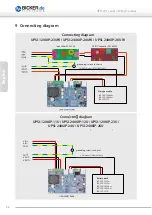
Page 44: ...2U UPSI 1208IP 23U UPSI 2406 24U UPSI 2406IP 26U Connecting diagram UPSI 1208IP 23UW UPSI 2406IP 24UW UPSI 2406IP 26UW Connecting diagram UPSI 1208IP 11U UPSI 2406IP 12U UPSI 1208IP 23U UPSI 2406IP 24...

Page 45: ...in impedance L 50nH R 50m protection can be guaranteed Warning Disregarding of following issues can result in electric shock fire serious injury or death 1 The input voltage must be switched off and s...

Page 46: ...en the measured temperature at the sensor drops below the threshold value 13 Backup times The nominal backup times can be found within the according data sheets The battery packs show diverse characte...

Page 47: ...e 1 5s Status shutdown Waiting for shutdown completion 4 x flash pause 1 5s Status reboot Output is switched off and time runs until restart Reboot 5 x flash pause 1 5s Status No battery recognized ba...

Page 48: ...O4 batteries always a larger capacity than actually needed should be selected The less deep the packs are discharged the longer the service life lasts 17 Maintenance The UPS contains no serviceable pa...

Page 49: ...to shut down the operating system and can be controlled using the internal battery settings of the operating system If a shutdown based on time is desired the software UPSI HID Battery Parameter Sett...

Page 50: ...during normal operation Output Voltage Output voltage displayed always Output Current Current of application Battery Voltage Voltage at storage medium Battery Current Current at storage medium State...

Page 51: ...within this time there will be no action Maximum Backup Time 1s 3600 s in steps of seconds The maximum hold up time After this time the application will be disconnected This setting can be used for sy...

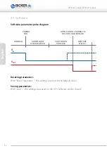
Page 52: ...eseting parameters With Reset Parameter the settings are reset to the default values Saving parameters With Save the settings are saved on the UPS Software can be closed NORMAL POWER FAIL APPLICATION...

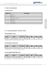
Page 53: ...ess Type Min Max Unit 0x62 GetDeviceName R char Transfer packet 0x01 0x03 0x01 0x62 0x04 GetFirmwareVersion 0x63 This read function returns the firmware version as string Cmd Name Access Type Min Max...

Page 54: ...Unit 0x01 GetOutputCurrent R Int32 0 32768 mA Transfer packet 0x01 0x03 0x02 0x01 0x04 GetInputVoltage 0x02 not connected at moment This read function returns the input voltage Cmd Name Access Type Mi...

Page 55: ...2 CV Shows that the charger is in constant voltage mode 3 UV Shows that the charger is in undervoltage lockout 4 CL Shows that the device is in input current limit 5 RV Reserved Bit 6 RV Reserved Bit...

Page 56: ...rrent 0x29 This read word function returns the measured charge current of the UPS Cmd Name Access Type Min Max Unit 0x29 GetChargeCurrent R Int16 32768 32768 mA Transfer packet 0x01 0x03 0x03 0x29 0x0...

Page 57: ...oEmpty 0x11 This read word function returns the predicted remaining battery capacity based on the present rate of discharge NOTE 65535 Battery is not being discharged Cmd Name Access Type Min Max Unit...

Page 58: ...ate 0x1B This read word function returns the pack s manufacturer date Cmd Name Access Type Min Max Unit 0x1B GetBatteryManufacturerDate R Uint16 0 65535 Transfer packet 0x01 0x03 0x04 0x1B 0x04 NOTE V...

Page 59: ...0x03 0x04 0x3C 0x04 GetBatteryCellVoltage3 0x3D This read word function returns the Cell 3 voltage Cmd Name Access Type Min Max Unit 0x3D GetBatteryCellVoltage3 R Uint16 0 65535 mV Transfer packet 0x0...

Page 60: ...ad sensor parameter values in mA 2 Maximum backup time values in seconds 3 Countdown timer to shut down the system when power fail occurs values in seconds Only on USB 4 Delay timer between output dis...

Page 61: ...0x04 NOTE The complete size of transferred data is number of id s size of parameter structure 7 10 bytes 70 bytes SetParameterIDx 0x01 to 0x06 This function sets the specified parameter Cmd Name Acces...

Page 62: ...ma Microsoft Corp Subject to errors and technical modifications Windows is a registered trademark of Microsoft Corporation Stand Issued 11 09 2019 Bicker Elektronik GmbH Ludwig Auer Stra e 23 86609 Do...

Reviews: