User’s Manual UPSI-B-2440
Bicker Elektronik GmbH
||
Tel. +49 (0)906 70595-0
||
www.bicker.de
||
24
E
n
g
lis
h
5 Installation and Commissioning
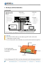
Connections
Attention
Do neither mount the DC UPS UPSI-B-2440 nor the battery pack BP-2450C
upside down.
Make sure sufficient convection is possible during operation.
on site
The distances illustrated
in the following figure
must be observed!
Note: Installing a fuse on site at both the input (F1) and output (F2) is recommended.
Interface connector: DSUB9
interface for RUPS2000
1 n.c.
2 Power Fail, collector
3 n.c.
4 Reference, Power Fail,
Battery low, Emitter
5 Battery low, collector
6 Shutdown input
7 Reference Shutdown
8 n.c.
9 n.c.
LED connector
1 GND
2 Green
3 Red
4 n.c.
DC connector
1 Battery: BAT (+)
2 Battery: BAT (–)
3 Output: OUT (+)
4 Output: OUT (–)
5 Input: IN (–)
6 Input: IN (+)
7 Ground: GND
TEMP connector
1 Temp. sensor battery
2 Temp. sensor battery
20 mm
20 mm
40 mm
40 mm
40 mm
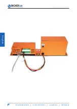
For the battery pack BP-2450C
no distances have to be observed for the installation!

