


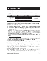


12 RIVA ADVANCE COMBI MANUAL
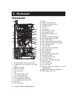
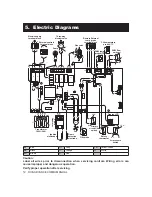
5. Electric Diagrams
Caution:
Label all wires prior to disconnection when servicing controls. Wiring errors can
cause improper and dangerous operation.
Verify proper operation after servicing.
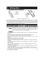
LD1
LD2
LD3
F1
F2
K1
K2
K3
K4
LD4
P6
T3
X1
X2
X3
X5
X6
X7
X10
X11
X12
X1
3
X17
X23
X24
P3
X14
X15
SB1
X16
X2
2
X9
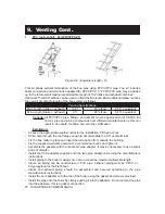
BL BR
W
GY
BL
W
GY
BR
1
2
3
L
N
Y/G BL
BR
R
BL
BR BL
Y/
G
BK BL
GY
Y/G BL
M
~
R
BL
BK
3
2
1
Y/
G
BL GY R BK BL
BL BK
Y/G
BK
BL
BK
1
3
4
Y/
G
BL BR
BR BL
W
O
W
GY
t
t
BK
R
R
BK
BL
BL
BL
BL
R
W
BL
W
BL
R
M
~
R BK
GY
W
R
GY
W
BK
t
BR
BL
W
BK
BK
W
BR
BL
COM
NO
R
R
R
R
GY
BK
GY
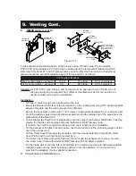
External controls
terminal block
Electric supply
terminal block
Pump
Three-way
diverter valve
Gas valve
CH temperature
probe NTC
DHW temp.
probe NTC
DHW flow
switch
Safety
thermostat
Flue probe
Primary
circuit flow
switch
Fan
Ignition
electrodes
Flame
detection
electrode
Transformer
120V~/24V~
Spark
Generator
R BK
R BK W GY
W
GY
Remote External
temp. probe
terminal block
R
R
W W
Display LCD
GY
BK
Air pressure
switch
COM
NC
NO
1
6
8
11
1
2
3
W
GY
BL
Blue
GY
Gray
Y/G
Yellow/Green
BK
Black
O
Orange
W
White
BR
Brown
R
Red


