


38 RIVA PLUS COMBI MANUAL
15. Commissioning Cont.
Checking the burner ignition:
15.6
Turn the boiler OFF.
•
Open the gas valve outlet pressure test point
•
15 (fi gure 15.5) and connect the gauge.
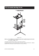
Turn the boiler ON positioning the function
•
selector B in the position shown in fi gure
15.7 and ensure that the room thermostat
is set to “heat demand”.
Figure 15.7
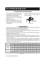
Loosen screws D and remove the service
•
panel (fi gure 15.8).
Figure 15.8
Watch the gauge and check to see if the
•
ignition pressure registerd corresponds
to the values given in the Technical Data.
Turn off the boiler and reignite it by turning
the function selector B to the 0 position and
then back to that indicated in fi gure 15.7.
Repeat this process two to three times
•
D
leaving 30 second intervals between each
ignition. Check the ignition pressures and
visually check that the burner lights uni-
formly and in a controlled manner.
To carry out the adjustment move the
•
function selector 3 to the OFF position
(Fig. 15.9) and use the device (ACC).
Figure 15.9
Adjust the gas pressure at the injectors to
•
the value indicated in the tables of section
2. By rotating the device clockwise the
pressure increases.
After the adjustment operations bring the
•
selector 3 of fi gure 15.9 back to the nor-
mal position (ON).
Reassemble the service panel.
•
Close the gas valve outlet pressure test
•
point 15 (fi gure 15.5).
Reassemble the front pannel of the case.
•
Important: after the checks all of the test
points must be sealed.
2
3
4
OFF
ON
1
ACC
RISC
+
+
Adjustment of the useful c.h. output:
15.7
Turn the boiler OFF.
•
Open the gas valve outlet pressure test point 15 (fi gure 15.5) and connect the gauge.
•
Turn the boiler ON positioning the function selector B in the position shown in fi gure 15.7
•
and ensure that the room thermostat is set to “heat demand”.
Loosen screws D and remove the service panel (fi gure 15.8).
•
To carry out the adjustment use the adjustment device (RISC) with the help of a screwdriver.
•
By rotating the device clockwise the pressure increases.
•
Adjust the gas pressure at the burner to the value according to the useful c.h. output wanted (Tab. 15.1).
•
Reassemble the service panel.
•
Close the gas valve outlet pressure test point 15 (fi gure 15.5).
•
Reassemble the front pannel of the case.
•